Before putting the instrument into operation
VF1807090083 EN revision 34
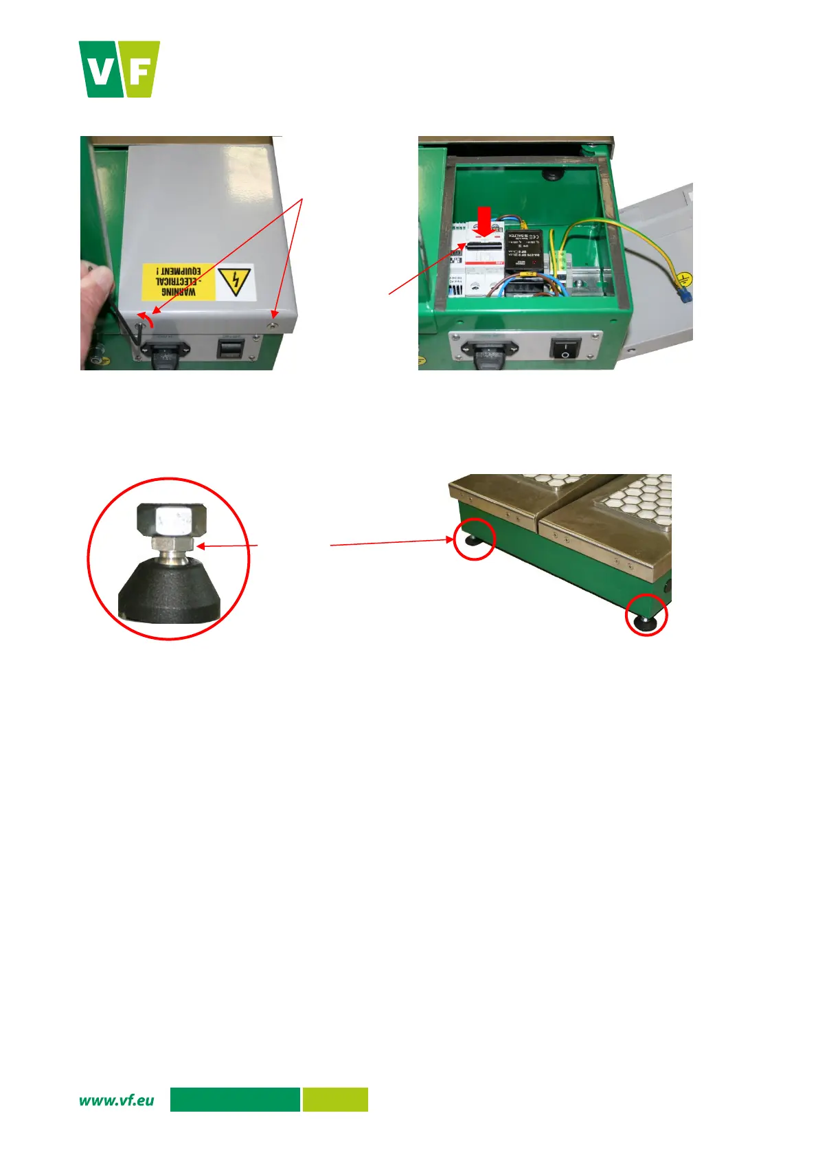
Fig. 10 Removal of the cover at the back part of the base and actuation of the FZ1 breaker
Use adjustable legs, placed in the corners of the instrument base, to adjust the position of the
instrument in the place of installation.
Fig. 11 Adjustable legs for proper positioning of the instrument
5.6. Operation verification
5.6.1 Instrument actuation
Connect the instrument to the AC mains, see Chapter 5.5, make sure that the FZ1 circuit breaker
is at its “on” position and for the version with the main switch, turn the main switch into the “I”
position. The red LED lights up on the monitor.
When the PLC operating system boots up, the instrument configuration and detector settings are
loaded and the background is measured. The red indicator lamp is lit and the green lamp is flashing.
The instrument is ready for use when the basic screen is shown on the display (Fig. 12) and when
the green indicator alone is permanently lit.