EasyManua.ls Logo

VF HF-50 - Fig. 7 Terminal Connectors on the Rear Side of the Box with the PLC; Fig. 8 Terminal Connectors on the Back of the Base; Tab. 4 Terminal Connectors

VF HF-50
94 pages
Print Icon
To Next Page IconTo Next Page
To Previous Page IconTo Previous Page
Loading...
General description
VF1807090083 EN revision 30
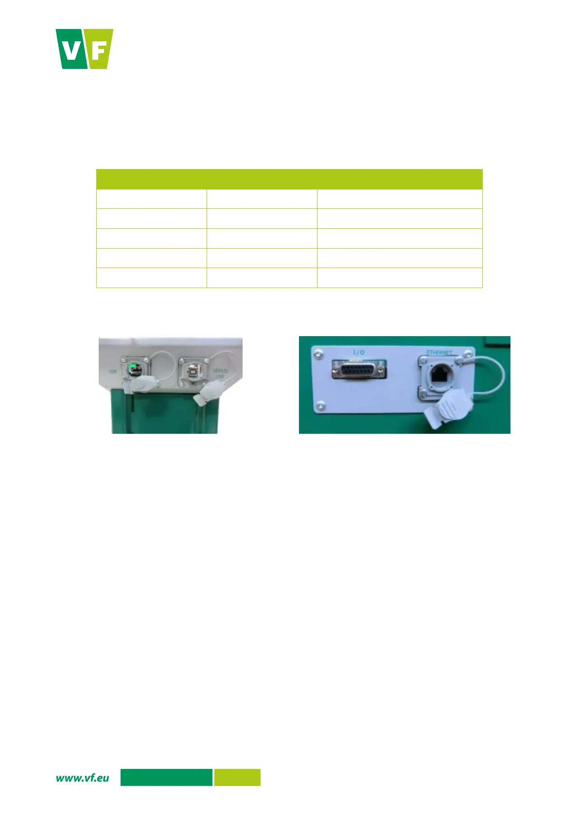
4.3.1 Connectors, description and location
A summary of instrument connectors is given in Tab. 4. The USB Service connector serves for connecting
a service PC. The I/O connector serves for connecting to technology using five relay outputs and two digital
inputs. The wiring diagram and a description of the contacts on the I/O connector are shown in the Annex D
to this document.
Identification
Connector type
Description
Ethernet
RJ-45
Service Ethernet
I/O
CAN15F
Technology connection
USB
USB
Connection of USB Flash Drive
Service USB
USB
Connection of Service PC
-
T01-0580-S07
Frisker connection
Tab. 4 Terminal connectors
Fig. 7 Terminal connectors on the rear side of the box
with the PLC
Fig. 8 Terminal connectors on the back of the base

Table of Contents