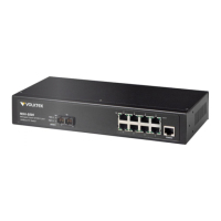
VOLKTEK NSH-5509 MANAGED 8-PORT 10/100 + 1-PORT 100-FX SWITCH
3.4 Powering On the Unit
The Switch uses an AC 100~240V or DC power supply of 9~32V DC. The power and
redundant power connection is provided via a terminal block located at the top of the
Switch. The Switch’s power supply automatically self-adjusts to the local power source
and may be powered on without having any or all LAN segment cables connected.
Check the front-panel LEDs as the device is powered on to verify that the Power
LED is lit. If not, check that the power cable is correctly and securely plugged in.
3.5 Connecting Fiber Cable
When connecting a fiber cable to the 100BASE-FX port on the Switch, be sure the
correct type of connector (ST or SC) is used. Follow the steps below to properly connect
fiber cabling:
1. Remove and keep the fiber port’s (ST/SC) rubber covers. When not connected
to a fiber cable, the rubber cover should be replaced to protect the fiber optics.
2. Check that the fiber terminators are clean. You can clean the cable plugs by
wiping them gently with a clean tissue or cotton ball moistened with a little
ethanol. Dirty fiber terminators on fiber optic cables will impair the quality of the
light transmitted through the cable and lead to degraded performance on the
port.
3. Connect one end of the cable to the ST/SC port on the Switch and the other
end to the fiber port of the other device.
Note: When inserting the cable, be sure the tab on the plug clicks into
position to ensure that it is properly seated.
Check the corresponding port LED on the Switch to be sure that the connection is valid.
(Refer to the LED chart).
3.6 Connecting Copper Cable
The 10/100Base-T RJ-45 Ethernet ports fully support auto-sensing and auto-negotiation.
1. Insert one end of a Category 3/4/5/5e (see recommendation above) type twisted-
pair cable into an available RJ-45 port on the Switch and the other end into the
port of the network node.
2. Check the corresponding port LED on the Switch to ensure that the connection is
valid. (Refer to LED chart)
3.7 Connecting the Console Port Cable
The console port (DB-9) provides the out-of-band management facility.
1 Use null modem cable to connect the console port on the Switch and the other
end into the COM port of the computer.
11
 Loading...