20
IMPORTANT!
Should you for any reason not wish to use the
start lock function, forfeiting the extra security
the system offers, isolate and insulate the
yellow wire no. 6 in the black cable.
Yellow wire no. 6 shall be attached to terminal
no. 85 on the relay. When the gear lever is in
neutral position, there is neg.(-) voltage in yellow
wire no. 6, the relay switches on, and the engine
can be started.
From the ignition key input pos.(+) (coming from
the engine’s cable harness), run a new wire no.
7 to the relay terminal no. 86, which always has
positive voltage as long as the engine’s main
switch is on.
Cut wire no. 8 (in the engine’s cable harness),
which runs from the engine’s ignition key to the
engine and controls the start signal to the
solenoid, and connect one end to terminal no.
87 on the relay and the other to no. 30 on the
relay.
NB! The Volvo Penta 24 V relay is of the
changeover type and has 5 terminal pins. Do not
use Pin 87a, but rather leave it unconnected
(Insulated).
Do not use the boat engine relay in this
connection.
When the boat has several operating stations
with start function, the relay should be connected
to the engine’s cable harness (after the engine
and before the harness branches off to the
various stations, e.g. wheelhouse, fly bridge,
etc.). In this way, one relay ensures that the start
lock function works for all operation stations.
There are two types of starting lock relay: one for
12 V, 40 A, which is approved for installation in
areas where there may be flammable gases,
and one that is not explosion proof, i.e. a 24 V, 20
A relay. NB! Other relays with built-in diodes
and other functions may interfere with or
damage the Volvo Penta System. Do not use
other relays.
Remaining wires
Wire no. 9 is the pos.(+) lead from the boat engine to
the ignition key.
Wire no. 10 is the main lead from the start battery group
and the main switch to the start motor.
Wire no. 11 is the neg.(-) cable between the batteries.
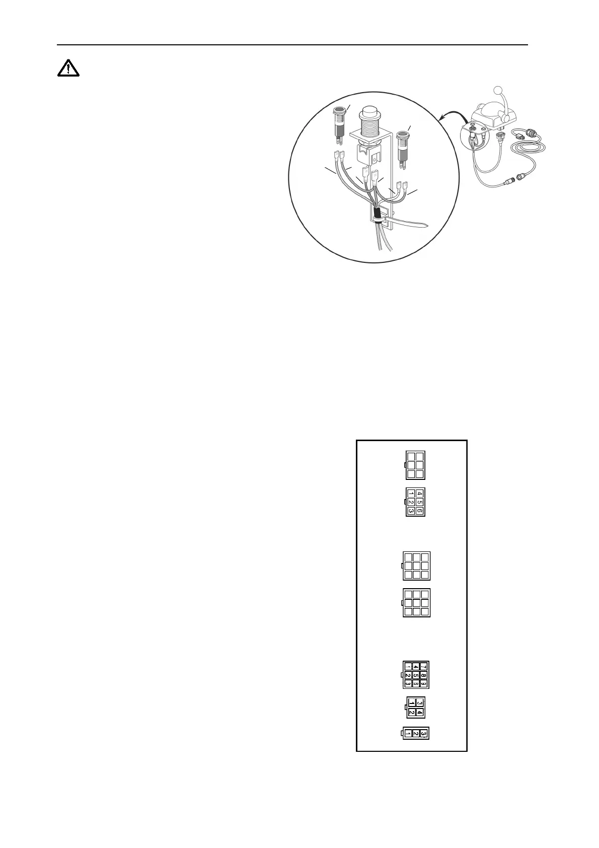
Signal cable
Connect the adapter cable (Y-cable) to the control and
the control panel, respectively (see figure 4). Affix the
adapter cable to the mounting arm of the panel with the
accompanying cable tie. Then connect the signal cable
to the adapter cable and run the signal cable to the
drive unit/electronic unit.
FIG. 4
Detach the electronic unit (four screws) from the drive
unit, and connect the contact cables to the rear of the
electronic unit. See fig. 5. Connect the cables as appro-
priate from wheel house to Control 1, from the fly bridge
to Control 2 and from any further operating position to
Control 3.
FIG. 5 REAR SIDE OF THE
ELECTRONIC UNIT
Brown
White
Blue
Pink
Brown
Gear
Throttle
Control 3
Control 2
Control 1
Battery
Ignition
Rear side of the electronic unit
Brown
Installation Instructions
Green diode
Red diode
 Loading...