8
SYSTEM CALIBRATION
System calibration must be carried out after installation
and during the annual function test. Calibration means
programming all data for the system’s various settings
into the electronic unit’s memory.
WARNING!
Never calibrate while the engine is running.
Two separate calibrations must be performed: system
calibration and control calibration.
System calibration
Use the buttons and display on the electronic unit to
perform system calibration. Detach the drive unit cover.
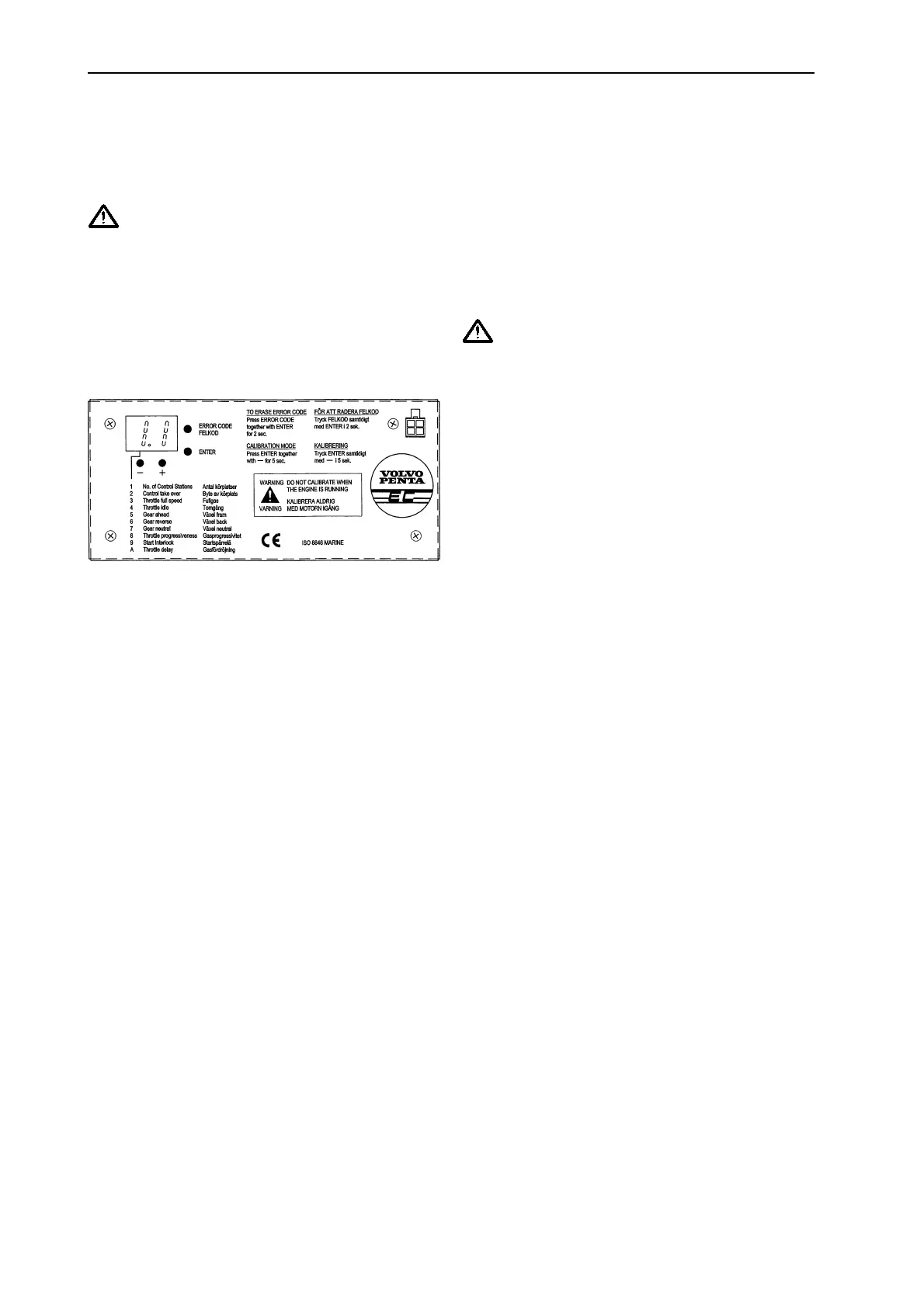
FIG. 6
The first figure on the display indicates which function is
being set. See the figure above. The second states the
current setting of the function in question.
Find out whether the engine’s throttle is pulling or
pushing and which is forward and reverse on the
reverse gear before starting the calibration.
An optional 4 m extension cord can be ordered to
facilitate system calibration. With the extension, the
electronic unit can be detached from the drive unit and
then employed as a “Remote control” when setting
throttle and gear functions.
When setting the stroke length of the mechanical cables
to match the movements of the throttle and gear arm, it
can be adjusted using the (+) and (-) buttons on the
electronic unit. (-) = actuator in, (+) = actuator out.
NB! When adjusting the actuators, take care so as not
to set them too tightly against their respective
mechanical stops. Should the actuators begin to
make noise when set, they are too tight and will
need to be “backed off” (within 10 seconds);
otherwise, the actuator will jam. Should the
actuators jam anyway, follow instructions on page
15.
Starting system calibration
a. Switch off all voltage to the system and ignition
and wait 10 seconds.
b. Switch on the Main pos. (+) and ignition but not
the backup pos.(+).
c. Enter the program by holding down the Enter
button and the (-) button at the same time for 5
seconds. Release, and the display lights up.
1. Setting the number of controls
The display now shows 1.1, which means that one
control can be connected. To select two controls, press
the (+) button once so that 1.2 appears on the display.
For three controls, press the (+) button again so that 1.3
appears.
2. Setting “station changeover” options
Press Enter and 2.0 appears, which means that
changeover is only possible in neutral. Press (+) so that
2.1 appears on the display = changeover underway is
now programmed.
WARNING!
When performing a changeover at speed, the
active operating position must not be left
unmanned.
3. Setting full throttle position
Press Enter. A value between 3.3 and 3.7 will appear on
the display.
3.3 = actuator fully retracted.
3.7 = actuator fully extended. Adjust the actuator
position using the (+) and (-) buttons.
4. Setting idle position
Press Enter. A value between 4.3 and 4.7 will appear on
the display.
4.3 = actuator fully retracted.
4.7 = actuator full extended. Adjust using the (+) and (-)
buttons.
5. Setting forward gear position
Press Enter. A value between 5.3 and 5.7 will appear on
the display.
5.3 = actuator fully retracted.
5.7 = actuator fully extended. Adjust using the (+) and (-)
buttons.
6. Setting reverse gear position
Press Enter. A value between 6.3 and 6.7 will appear on
the display.
6.3 = actuator fully retracted.
6.7 = actuator fully extended. Adjust using the (+) and (-)
buttons.
7. Setting neutral gear position
Press Enter. A value between 7.3 and 7.7 will appear on
the display.
7.3 = actuator fully retracted.
7.7= actuator fully extended. Adjust using the (+) and (-)
buttons.
8. Setting throttle progression (5 different curves)
Press Enter. 8.0, 8.1, 8.2, 8.3 or 8.4 will appear on the
display. Each figure combination indicates a specific
throttle curve. See diagram page 9. Select throttle curve
using the (+) and (-) buttons. Normal standard curve =
8.1.
9. Setting starting lock function
Press Enter. 9.0 or 9.1 will appear on the display. Using
the (+) and (-) buttons, select 9.0 if no starting lock relay
is fitted or 9.1 if a starting lock relay has been installed.
User Instructions
 Loading...