14 Making Fluidic Connections to the 600E Pump
The following sections describe setting up your eluent reservoirs using these components.
It covers:
• Setting up the eluent reservoir
• Connecting eluent and sparge tubes to the reservoir
• Connecting the vent tube to a fume hood
Setting Up the Eluent Reservoir
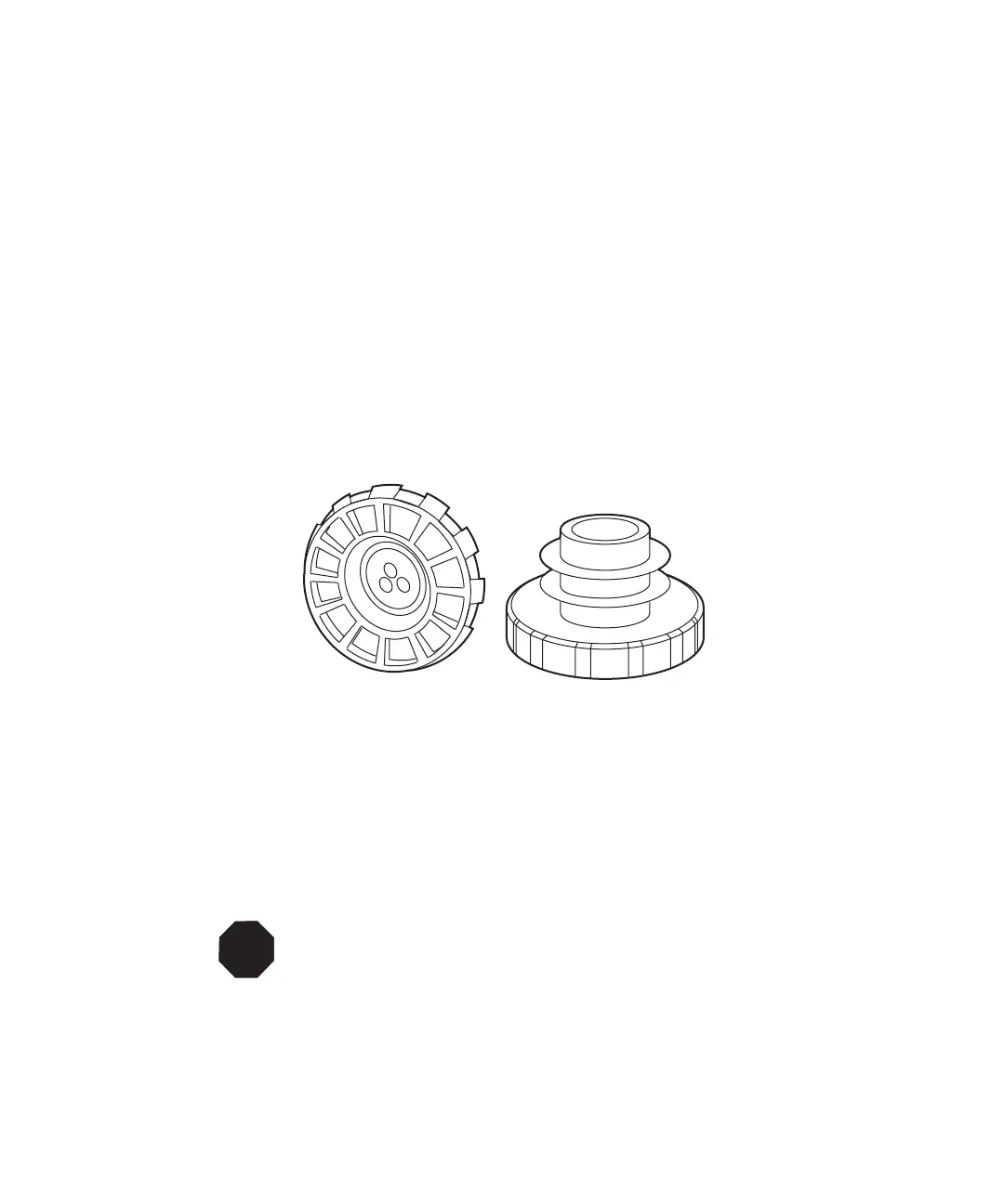
Eluent reservoir caps (Figure 2-6) help maintain a continuously sparged environment in
the reservoirs (bottles).
Each reservoir cap has three feather-edged holes to produce a positive seal around the
eluent, sparge, and vent tubes. The reservoir caps are supplied for a 1-L bottle size but are
also available for a 4-L bottle size.
Figure 2-6 Eluent Reservoir Caps
Choose eluent reservoirs which provide a snug fit for the reservoir caps. Waters
recommends 1-L bottles.
1. Position the bottles in a convenient location, preferably at a higher level than the
pump heads. Eluent bottles must be placed above the inlet manifold. There are
optional bottle racks for this purpose as listed in Appendix A, Spare Parts.
2. Remove the protective wrapping from:
• Four Teflon
tubing lines marked Solvent A, B, C, D.
• Four Teflon tubing lines marked Sparge A, B, C, D.
STOP
Attention: Avoid placing the eluent bottles on top of the system unless they
are in a container that can hold the total volume of all of the eluents in case
bottle leakage occurs. Leakage or spillage may cause damage to the
system.