54 Making Electrical Connections to the 600 Controller
You define S1 through S4 operation using the:
• Program Event screen (for time-based activation)
• Isocratic or Direct Control screen (for immediate activation)
Refer to Section 5.1 or 6.2 of the 600E Multisolvent Delivery System User’s Guide.
Connections
To control an external device using one of the S1 through S4 screw terminals, connect the
event cable (provided in the 600E Startup Kit) as outlined below:
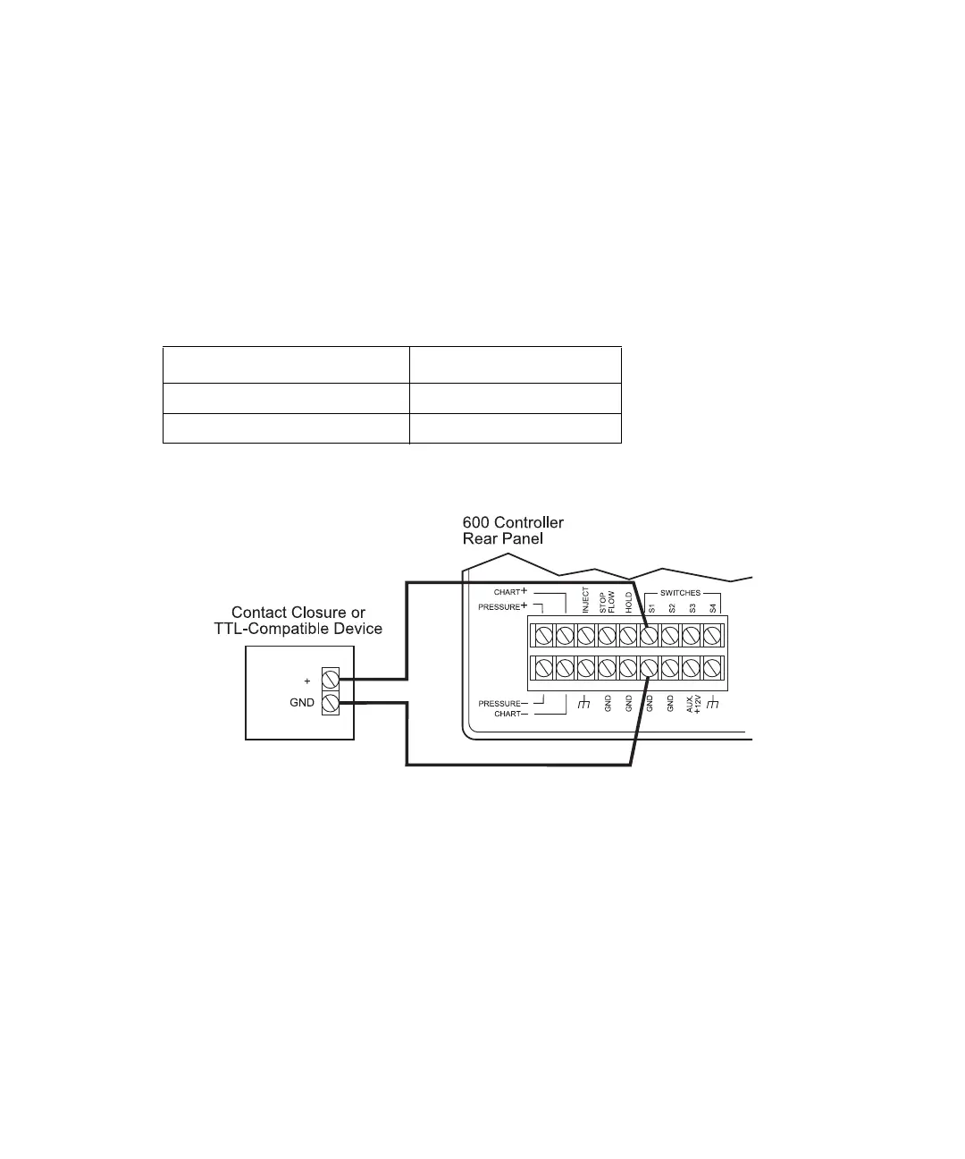
Figure 3-15 illustrates connecting an external device to the 600 controller S1 terminal.
Figure 3-15 Connecting an External Device to 600 Controller Switch S1 Terminals
Connecting External Devices to Aux +12 V Power
For external devices requiring an auxiliary +12 V power source, use the Aux +12 V
terminal on the 600 controller.
Note: The maximum current available from the 12 V power source (divided among all the
devices in use on S1 through S4) is 1.5 A. The maximum current capacity of any single
event (S1 through S4) is 1.0 A.
600 Controller Connection External Device
S1, S2, S3, or S4 (red lead) +
Gnd (black lead) Gnd