Home
Wecon
Servo Drives
VD2F-010SA1P
Page 49
Wecon VD2F-010SA1P - Page 49
133 pages
Manual
Save Page as PDF
To Next Page
To Next Page
To Previous Page
To Previous Page
Loading...
W
econ
VD2
SA
Series
Servo
D
rive
s
Manua
l
(Lite
V1.1)
WECON
technolog
y
Co.,
Ltd
43
2
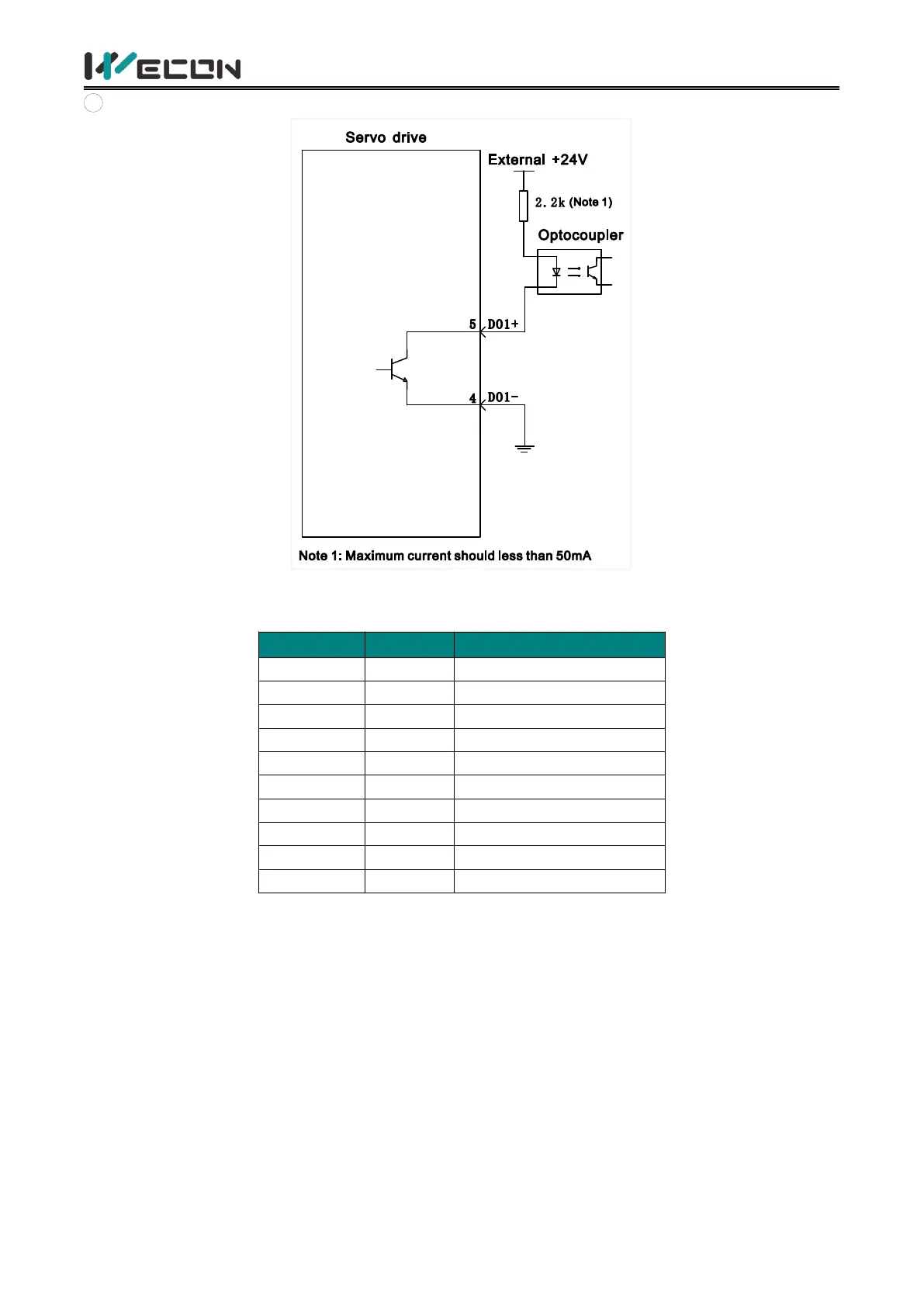
When
the
control
d
evice
(HMI/PLC)
is
opto
coupler
input
Figure
4-22
Optoc
oupler
input
(2)
VD2F
servo
drive
Pin
number
Pin
name
Default
function
5
DI1
Servo
enable
10
DI2
Fa
ult
and
alarm
clearance
4
DI3
Forwar
d
drive
prohibited
9
DI4
Rev
erse
drive
p
rohibite
d
3
SS
Pow
er
input
(24V)
2
DO1
Rot
ation
detection
7
DO2
Fau
lt
signal
1
DO3
Servo
is
ready
6
DO4
Positioning
complete
d
8
DOCOM
Do
comm
on
t
erminal
T
able
4-
17
DI/DO
signal
description
48
50
Table of Contents
Main Page
1.Safety reminder
7
1.1 Safety precautions
7
1.2 Precautions for storage and transportation
8
1.3 Precautions during installation
8
1.4 Precautions during wiring
9
1.5 Precautions during operation
9
1.6 Precautions during maintenance and inspection
10
2.Product Information
11
2.1 Servo drives
11
2.1.1 Servo drive model naming
11
2.1.2 The composition of servo drive
13
2.1.3 Specification of servo drive
15
2.2 Servo motors
16
2.2.1 Servo motor model naming
16
2.2.2 Composition of Servo motor
16
2.2.3 Specification of servo motor
17
3.Installation of servo drive and motor
18
3.1 Installation of servo drive
18
3.1.1 Dimensions (Unit: mm)
18
3.1.2 Installation site
19
3.1.3 Installation environment
19
3.1.4 Installation matters
20
3.2 Installation of servo motor
23
3.2.1 Installation dimensions (unit: mm)
23
3.2.2 Installation site
26
3.2.3 Installation environment
26
3.2.4 Installation precautions
26
4.Wiring
28
4.1 Main circuit wiring
28
4.1.1 Main circuit terminals
28
4.1.2 Power wiring
31
4.1.3 Precautions for main circuit wiring
35
4.2 Power line connection of servo drive and servo
35
4.2.1 Power line
35
4.2.2 Brake device cable
36
4.3 Encoder cable connection of servo drive and se
36
4.4 Servo drive control input and output wiring
40
4.4.1 CN2 pin distribution
40
4.4.2 Wiring diagram of each mode
42
4.4.3 Position instruction input signal
44
4.4.4 Analog input signal
46
4.4.5 Digital input and output signals
47
4.4.6 Brake wiring
52
4.5 Communication signal wiring
52
4.5.1 Communication connection with servo host com
53
4.5.2 Communication connection with PLC and other
55
5.Panel
56
5.1 Panel composition
56
5.2 Panel display
56
5.2.1 Display switching
57
5.2.2 Status display
57
5.2.3 Parameter display
57
5.2.4 Fault display
59
5.2.5 Monitor display
60
5.3 Panel operation
61
5.3.1 Parameter setting
61
5.3.2 Jog operation
62
5.3.3 Factory reset
63
6.Parameters
64
Group P00 Basic settings
64
Group P01 Control parameters
68
Group P02 Gain adjustment
72
Group P03 Self-adjusting parameters
73
Group P04 Vibration suppression
74
Group P05 Signal input and output
76
Group P06 DI/DO configuration
80
Group P07 multi-segment position
84
Group P10 Accessibility
91
Group P12 Communication parameters
93
Group P13 Communication input and output terminal
94
Group U0 Universal monitoring
95
Group U1 Warning monitoring
100
Group U2 Device monitoring
102
7. Malfunctions
104
7.1 Faults and warnings handling at startup
104
7.1.1 Position control mode
104
7.1.2 Speed control mode
105
7.1.3 Torque control mode
106
7.2 Faults and warnings handling during operation
107
7.2.1 Overview
107
7.2.2 Fault and warning code table
108
8.Modbus register address
116
Group P00 Basic settings
116
Group P01 Control parameter
117
Group P02 Gain adjustment
119
Group P03 Self-adjustment parameters
119
Group P04 Vibration suppression
120
Group P05 Signal input and output
121
Group P06 DIDO configuration
122
Group P07 multi-segment position
124
Group P10 Accessibility
128
Group P12 Communication parameters
129
Group P13 Virtual input terminal
129
Group U0 Monitoring parameters
130
Group U1 Warning monitoring
132
Group U2 Device monitoring
133
Related product manuals
Wecon VD2 SA Series
171 pages
 Loading...