34
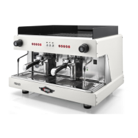
Wegaconcept
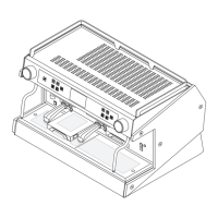
Technical manual
MALFUNCTION CAUSE SOLUTION
ALL THE LEDS OF ALL THE PUSH BUTTON
PANELS ARE FLASHING
After a few minutes, automatic lling with water is
stopped:
t The device is in time-out.
t No water in mains.
t The tap for the automatic level device is closed.
t Some of the hoses in the circuit are clogged.
t The probe and/or the mass are disconnected.
t Turn the machine o and then back on.
t Open the water supply tap.
t Open the automatic level device tap.
t Check and replace the defective hoses.
t Check and restore the connections.
SHUTDOWN OF THE ELECTRONIC SYSTEM
t The control unit fuse F4 is burned out.
t One of the volumetric dosing device's contacts is
grounded
t Replace fuse F4
t Check the connection of the volumetric dosing device
THE PUMP LEAKS WATER
t Poor mechanical grip of the shaft or O-Ring seal.
t The inlet and outlet connections are loose.
t The hex nut of the pressure relief valve or lter is loose.
t The seal or O-Ring of the pressure relief valve or lter
is faulty.
t Check the status of the pump and take any corrective
action which may be required.
t Tighten the connections.
t Tighten the hex connection of the pressure relief
valve and lter.
t Replace the seal and O-Ring, taking care not to change
the calibration of the valve.
THE MOTOR STOPS SUDDENLY OR THE
THERMAL PROTECTOR INTERVENES DUE
TO OVERLOAD
t Lime scale and mineral build-ups in the pump have
caused it to jam.
t The pump and motor are not aligned.
t The motor is faulty.
t The motor is wired with non-conforming voltage.
t Check the status of the pump and replace it, if neces-
sary.
t Install the motor-pump joint.
t Replace the motor.
t Ensure the power supply voltage of the motor is
correct.
THE PUMP FUNCTIONS BELOW NOMINAL
CAPACITY
t The inlet is clogged, perhaps only partially.
t The rotation sense of the pump is incorrect.
t The pressure relief valve is not properly calibrated.
t The motor runs at low RPM.
t The inside of the pump is damaged due to the inltra-
tion of foreign materials.
t Clean the lter holder.
t Check the engine.
t Calibrate the relief valve.
t Check the voltage or replace the motor.
t Replace the pump.
THE PUMP IS NOISY
t The pump and motor are not aligned.
t The seal or O-Ring of the pressure relief valve or lter
is faulty.
t The joint, the coupling screw or the V-shaped clamp
are loose.
t The inlet is clogged, perhaps only partially.
t The hex nut of the pressure relief valve or lter is loose.
t Install the motor-pump joint.
t Replace the seal and O-Ring, taking care not to change
the calibration of the valve.
t Align and tighten the components which are loose.
t Clean the lter holder.
t Tighten the hex connection of the pressure relief
valve and lter.
THE CUP IS DIRTY WITH SPLASHED
COFFEE
t Steam pockets in the delivery system.
t Air pockets in the hydraulic circuit.
t Coee is ground too coarsely
t Reduce the water temperature.
t Check the cause and eliminate the problem.
t Adjust the grinding suitably.