CHANGING
HERTZ
AND
VOLTAGE
.A
CAUTION:
As a
precaution
against
an
URlntlmttonat
statt,shutoftlM#AmpDt:lmlak8r-
..-
on
the
control
panel.
1.
Refer to
the
previous
page
that
illustrates
the
various
AC
voltage
output
configurations
for
both
the
60
Hertz
and
50
Hertz applications.
Select
the
configuration
for
the
HertzIVoltage
required.
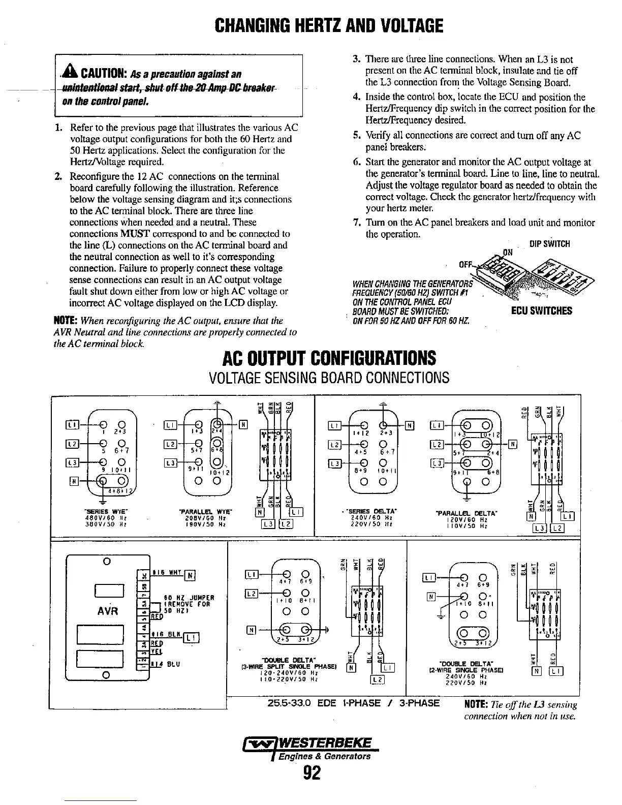
2.
Reconfigure
the
12
AC
connections
on
the
tenninal
board carefully
following
the
illustration.
Reference
below the voltage sensing diagram and it;s connections
to
the
AC
tenninal
block.
There
are
three
line
connections
when
needed
and
a
neutral.
These
connections
MUST
correspond
to
and
be
connected
to
the
line (L) connections
on
the
AC
tenninal board
and
the
neutral connection
as
well
to
it's corresponding
connection.
Failure
to
properly
connect
these
voltage
sense connections
can
result
in
an
AC
output
voltage
fault
shut
down
either
from
low
or
high
AC
voltage
or
incorrect
AC
voltage
displayed
on
the
LCD
display.
NOTE:
When reconfiguring the
AC
output. ensure that the
AVR Neutral
and
line connections are properly connected to
the
AC
terminal block.
3. There are
three line connections. When an L3 is not
present
on
the
AC
tenninal
block,
insulate
and
tie
off
the
L3
connection
from
the
Voltage
Sensing
Board.
4.
Inside
the
control
box,
locate
the
ECU
and
position
the
HertzlFrequency
dip
switch
in
the
correct position
for
the
HertzlFrequency
desired.
5.
Verify
all
connections
are
correct
and
tum off
any
AC
panel
breakers;
6.
Start
the
generator
and
monitor
Ule
AC
output
voltage
at
the generator's tenninal
board.
Line
to
line,
line
to
neutral.
Adjust
the
voltage
regulator
board
as
needed
to
obtain
the
correct
voltage.
Check
the
generator
hertz/frequency
with
your
hertz
meter.
7.
Turn
on
the
AC
panel
breakers
and
load
unit
and
monitor
the
operation.
WHEN
CHANGING
mE
GEN1'RATi~RS'~
FREQUENCY
(50160
HZ)
SWITCH
11
ON
mE
CONmOL
PANEL
ECU
.
BOARD
MUST
BE
SWITCHED:
.
ON
FOR
50
HZ
AND
OFF
FOR
60
HZ.
DIP
SWITCH
ECU
SWITCHES
AC
OUTPUT
CONFIGURATIONS
VOLTAGE
SENSING
BOARD
CONNECTIONS
o
AVR
o
~116WHT[EJ
60
HZ
JUMPER
IREMOVE
rOR
50
HZI
z
~
.
z
z •
~
0
lID
~
•
•
~
z
~
0
lID
~
0
~
~
.
.
,»
,,'
,,'
,.,
..
!TIl
0
v''''
f
IB
o·
~"'iO,
'f
1+10
8HI
'1111
-4'+
10
!
8+ , I
'III
II
0 0
II
II
0 0
"-
HI
IB
• I,
,
,\~
2:,
.\.
t.
o·
~
0
-oouBLE
DELTA~
z
~
13-W1RE
SPLIT SINGlE PHASE)
·OOUBLE
08..TA-
•
.
120·240V/60
H1
12·WIRE
SINGLE PHASE)
0
[Ii]
IIO-220V/SO
HI
240V/60
Hz
220V/50
HI
25.5-33.0 EDE I-PHASE / 3-PHASE
NOTE:
Tie
off
the
L3
sensing
connection when not in use.
-.,.y"
WESTERBEKE
Engines & Generators
92