DISASSEMBLY
I
ASSEMBLY
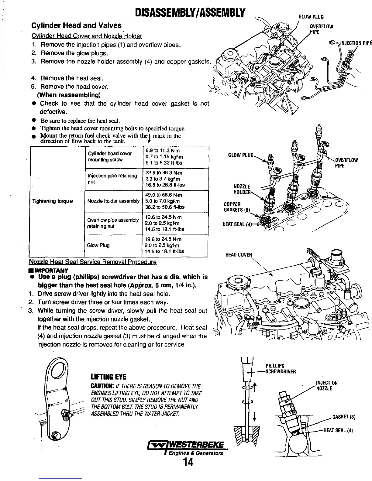
Cylinder Head and Valves
Cylinder Head Cover and Nozzle Holder
1.
Remove the injection pipes
(1)
and
overflow pipes.
2.
Remove the glow plugs.
3.
Remove the nozzle holder assembly
(4)
and copper gaskets.
4.
Remove the heat seal.
5.
Remove the head cover.
(When reassembling)
• Check to.
see
that the cylinder head cover gasket is not
defective.
•
Be
sure to replace the heat seal.
• TIghten the head cover mounting bolts to specified torque.
• Mount the return fuel check valve with the I mark in the
direction
of
flow back to the taok. t
Cylinder head cover
6.9 to 11.3
N·m
0.7
to
1.15 kgf·m
mounting
screw
5.1
to 8.32 It-Ibs
Injection
pipe
retaining
22.6 to 36.3 N·m
2.3 to 3.7 kgf·m
nut
16.6 to 26.8
It-Ibs
49.0
to 68.6 N·m
Tightening
torque
NOlzle holder assembly 5.0 to 7.0 kgf·m
36.2
to
50.6 It-Ibs
Overflow pipe assembly
19.6 to 24.5
N·m
2.0
to 2.5 kgf·m
retaining nut
14.5
to
18.1
It-Ibs
19.6 to 24.5 N·m
Glow Plug 2.0 to 2.5 kgf-m
14.5 to
18.1
It-Ibs
Nozzle Heat Seal Service Removal Procedure
•
IMPORTANT
•
Use
a
plug
(phillips) screwdriver
that
has
a dia.
which
is
bigger
than
the
heat seal hole (Approx. 6 mm, 1/4 in.).
1.
Drive screw driver lightly into
the
heat seal hole.
2. Turn screw driver three or four times each way.
3. While turning the screw driver, slowly pull the heat seal out
together with the injection nozzle gasket. .
If the heat seal drops, repeat the above procedure. Hmit seal
(4) and injection nozzle gasket
(3)
must be changed when the
injection nozzle is removed for cleaning or for service.
LIFTING
EYE
CAUTION:
IF
THERE
IS
REASON
TO
REMOVE
THE
ENGINES
LIFTING
EYE,
00
NOT
ATTEMPT
TO
TAKE
OUT
THIS
STUO.
SIMPLY
REMOVE
THE
NUT
AND
THE
BOTTOM
BOLT.
THE
STUD
IS
PERMANENTLY
ASSEMBLED
THRU
THE
WATER
JACKET.
o
GLOW
NOZZLE
COPPER
GASKETS
HEAT
SEAL
HEAD
COVER
Engines & Generators
14
PHilLIPS
_",IN,JEClrION
PIPE
PIPE
INJECTION
NOZZLE
GASKET
(3)
=:r.:3::s..\..L=-
HEAT
SEAL
(4)