STARTER
MOTOR
SERVICE
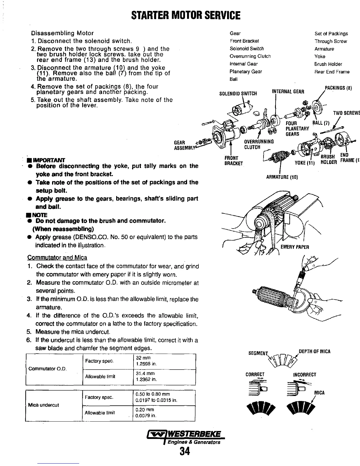
Disassembling
Motor
1.
Disconnect the solenoid switch.
2.
Remove the two through screws 9 ) and the
two
brush
holder lock screws. take out the
rear end frame (13) and the brush holder.
3.
Disconnect
the armature
(10)
and the yoke
(11). Remove also the
ball (7) from the tip
of
{he armature.
Gear
Front Bracket
Solenoid
Switch
Overrunning Clutch
Internal Gear
Planetary Gear
Sail
Set of Packings
Through Screw
Armature
Yoke
Brush
Holder
Rear End Frame
4.
Remove the set
of
packings (8), the four
planetary
gears and another packing.
SOLENOID
SWITCH
'~~~.':,~:~
5.
Take out the shaft assembly. Take note of the
position
of
the lever.
•
IMPORTANT
GEAR
..
_.-?
ASSEMBLY~
•
Before
disconnecting the yoke,
put
tally marks on the
yoke
and
the
front bracket.
• Take
note
of
the
positions
of
the set
of
packings and the
setup
bolt.
•
Apply
grease
to
the gears, bearings, shaft's sliding part
and
ball
.
•
NOTE
• Do
not
damage
to
the brush and commutator.
(When
reassembling)
•
Apply grease (DENSO.CO.
No.
50
or equivalent)
to
the
parts
indicated
in
the
illiJstration.
Commutator and Mica
1.
Check the contact face
of
the
commutator for
wear,
and
grind
the
commutator
with
emery paper
if
it
is
slightly
worn.
2. Measure the commutator
0.0.
with
an
outside micrometer
at
several points.
3.
If
the minimum
0.0.
is
less
than
the
allowable
limit,
replace
the
armature.
4.
If
the
difference
of
the
O.D.'s exceeds
the
allowable limit,
correct the commutator
on
a
lathe
to
the
factory specification.
5.
Measure the mica undercut.
6.
If the undercut
is
less
than
the
allowable limit, correct
it
with
a
saw blade and chamfer
the
segment edges.
Factory spec.
32mm
1.2598
in.
Commutator
0.0.
Allowable limit
31.4
mm
1.2362
in.
Factory spec.
0.50
to
0.80
mm
0.0197
to
0.0315
in.
Mica
undercut
Allowable limit
0.20
mm
0.0079 in.
-..yo"
WESTERBEKE
Engines & Generators
34
fi~\i~
FOUR
BAL~(7)
rl'-\ll.'I'I''''-""''
PLANETARY
FRONT
BRACKET
GEARS
ARMATURE
(10)
SEGMENT~OEPTH
OF
MICA
CORRECT
~
-
INCORRECT
~MICA
.;