ENGINE
ADJUSTMENTS
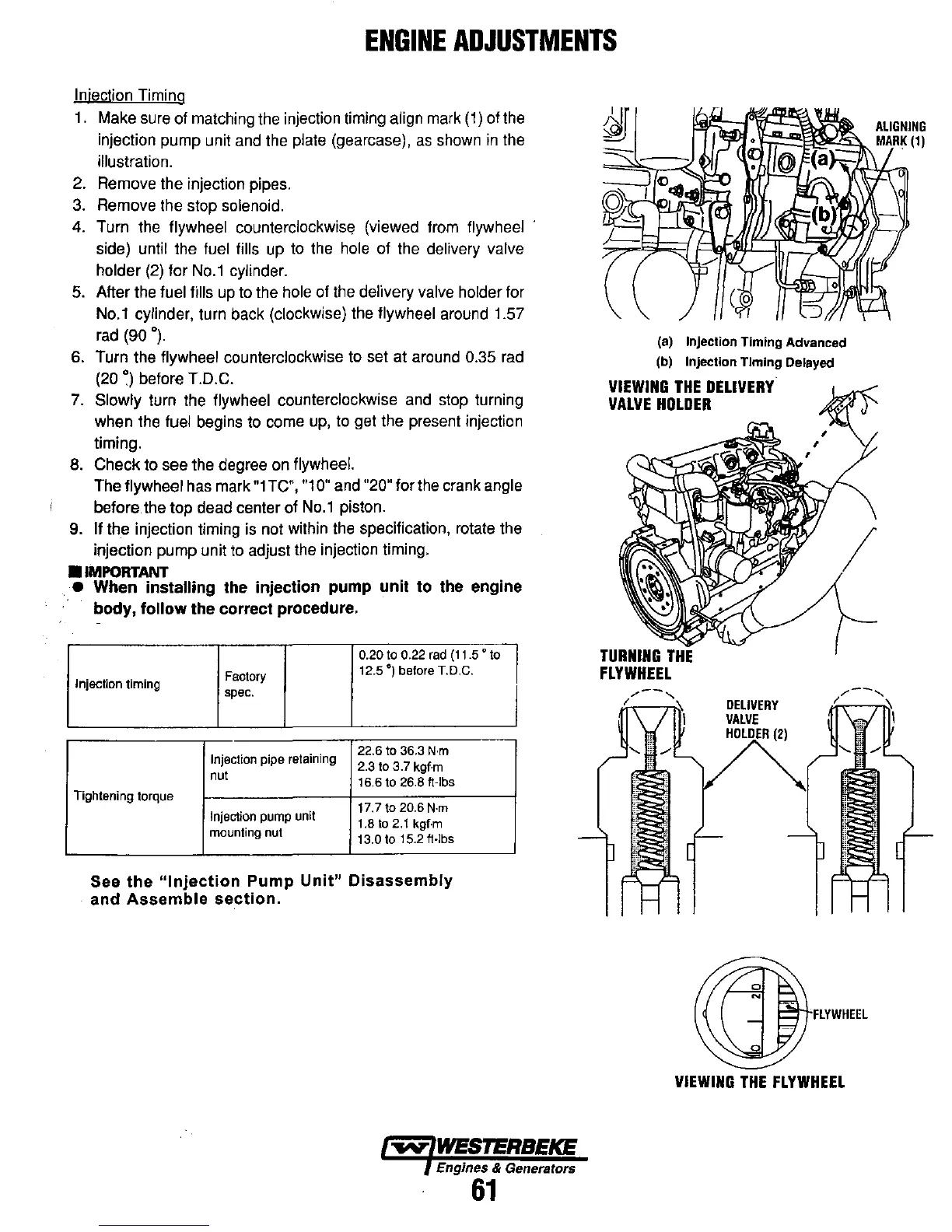
Injection Timing
1.
Make sure of matching the injection timing align
mark
(1)
of the
injection pump unit
and
the plate (gearcase),
as
shown
in
the
illustration.
2. Remove the injection pipes.
3.
Remove the stop solenoid.
4. Turn the
flywheel counterclockwise (viewed from flywheel
side)
until the fuel fills up to the hole of the delivery valve
holder
(2)
for
No.1
cylinder.
5.
After the fuel fills
up
to the hole of
the
delivery valve holder for
No.1
cylinder, turn back (clockwise) the flywheel around 1.57
rad
(90
0).
6.
Turn the flywheel counterclockwise to set at around 0.35
rad
(20
~)
before T.D.C.
7.
Slowly turn the flywheel counterclockwise
and
stop turning
when the
fuel begins to come
up,
to get the present injection
timing.
8. Check to see the degree
on
flywheel.
The flywheel has mark
"1
TC", "10" and "20" for the crank angle
before the top dead center of
No.1
piston.
9.
If the injection timing
is
not within the specification, rotate the
injection pump unit
to
adjust the injection timing .
•
IMPORTANT
•
When
installing
the
injection
pump
unit
to
the engine
body,
follow
the
correct
procedure.
0.20 to 0.22
rad
(t t
.5
" to
Factory
12.5")
before T.D.C.
Injection
timing
spec.
Injection pipe retaining
22.6 to 36.3
N·m
2.3 to 3.7 kgf·m
nut
16.6 to 26.8
ft-Ibs
Tightening torque
Injection
pump
unit
17.7 to 20.6
N·m
1.8 to
2.1
kgf·m
mounting
nut
13.0 to t 5.2 ft-Ibs
See
the
"Injection
Pump
Unit"
Disassembly
and
Assemble
section.
~
WESTERBEKE
Engines & Generators
61
(a)
Injection
Timing
Advanced
(b)
Injection
Timing
Delayed
VIEWING
THE
DELIVERY
VALVE
HOLDER
DELIVERY
VALVE
FLYWHEEL
VIEWING
THE
FLYWHEEL