ENGINE
ASSEMBLY
INSTRUCTIONS
ALTERNATOR
INSPECTION
When rebuilding the engine. the alternator should be cleaned
and inspected. The housing can be wiped
off
with a solvent
and the alternator tenninal studs should be cleaned with a
wire brush. Make certain the studs are tight and clean the
wiring
connections that connect to the wiring harness.
Thrn the rotor pulley by hand.
It
should turn smoothly.
Depending on when the alternator was last serviced. the
brushes may need replacing.
If
the alternator is at all suspect.
send it to a service shop for testing and overhaul. or refer
to
the more detailed alternator section in this manual.
HEAT
EXCHANGER
(MARINE
ENGINES/GENERATORS)
Install the heat exchanger. replace the heat exchanger zinc
and attach new hoses with new clamps to the cooling system.
Refer to the
COOllNG SECTION in this manual for HEAT
EXCHANGER service.
MARINE
TRANSMISSION
(MARINE
ENGINES)
1. Assemble Ibe
damper
plate
to
the
flywheel.
2. Re-install
Ibe
marine
transmission
and
fill with the
correct
amount
of
fluid. Do
not
overfill.
MOlE:
Some transmissions. such as the Borg
Warner
Velvet
Drive require oil coolers.
Oil
coolers should be
cleaned,
pressure tested and repainted at engine overhaul.
The
transmission oil cooler hases should also
be
inspected.
ReJer
to
the text on HEAT EXCHANGERS.
RADIATORS
The
radiator, cleaned. flushed, and pressure tested can be
assembled to the generator mounting rails. The fan can be
assembled to the engine.
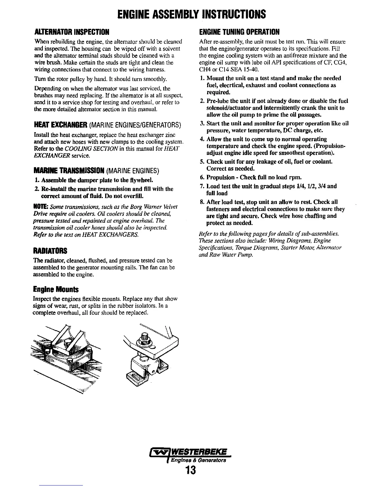
Engine
Mounts
Inspect the engines flexible mounts. Replace any that show
signs
of
wear, rust, or splits in the rubber isolators.
In
a
complete overhaul. all four should be replaced.
ENGINE
TUNING
OPERATION
After re-assembly, the unit must be test run. This will ensure
that the engine/generator operates to its specifications. Fill
the engine cooling system with an antifreeze mixture and the
engine oil sump with lube oil
API specifications
of
CF,
CG4.
CH4
or
CI4
SEA 15-40.
1.
Mount
the
unit
on
a
test
stand
aud
make
the
needed
fuel, elecrtical,
exhaust
and
coolant connections
as
required.
2.
Pre-lube
the
unit
if
not
already
done
or
disable
the
fuel
solenoid/actuator
and
intermittently
crank
the unit to
allow
the
oil
pump
to
prime
the oil passages.
3.
Start
the
unit
and
monitor
for
proper
operation
like oil
pressure,
water
temperature,
DC
charge, etc.
4.
Allow
the
unit
to come
up
to
normal
operating
temperature
and
check the engine speed. (Propulsion-
adjust
engine idle speed
for
smoothest operation).
5.
Check
unit
for
any
leakage
of
oil, fuel
or
coolant.
Correct
as
needed.
6.
Propulsion -
Check
fuJI
no
load
rpm.
7.
Load
test
the
unit
in
gradual
steps
114, 112,
3/4
and
full
load
8.
After
load
test,
stop
unit
an
allow to rest.
Check
all
fasteners
and
electrical connections to
make
sure
they
are
tight
and
secure.
Check
wire hose challing
and
protect
as
needed.
Refer
to
the following pages for details
of
sub-assemblies.
These
sections
also
include:
Wiring
Diagrams,
Engine
Specifications.
Torque
Diagrams.
Starter
Motor.
Alternator
and Raw
Water
Pump.
Engines & Generators
13