GENERAL
DESCRIPTION
FORK
LEVER
2
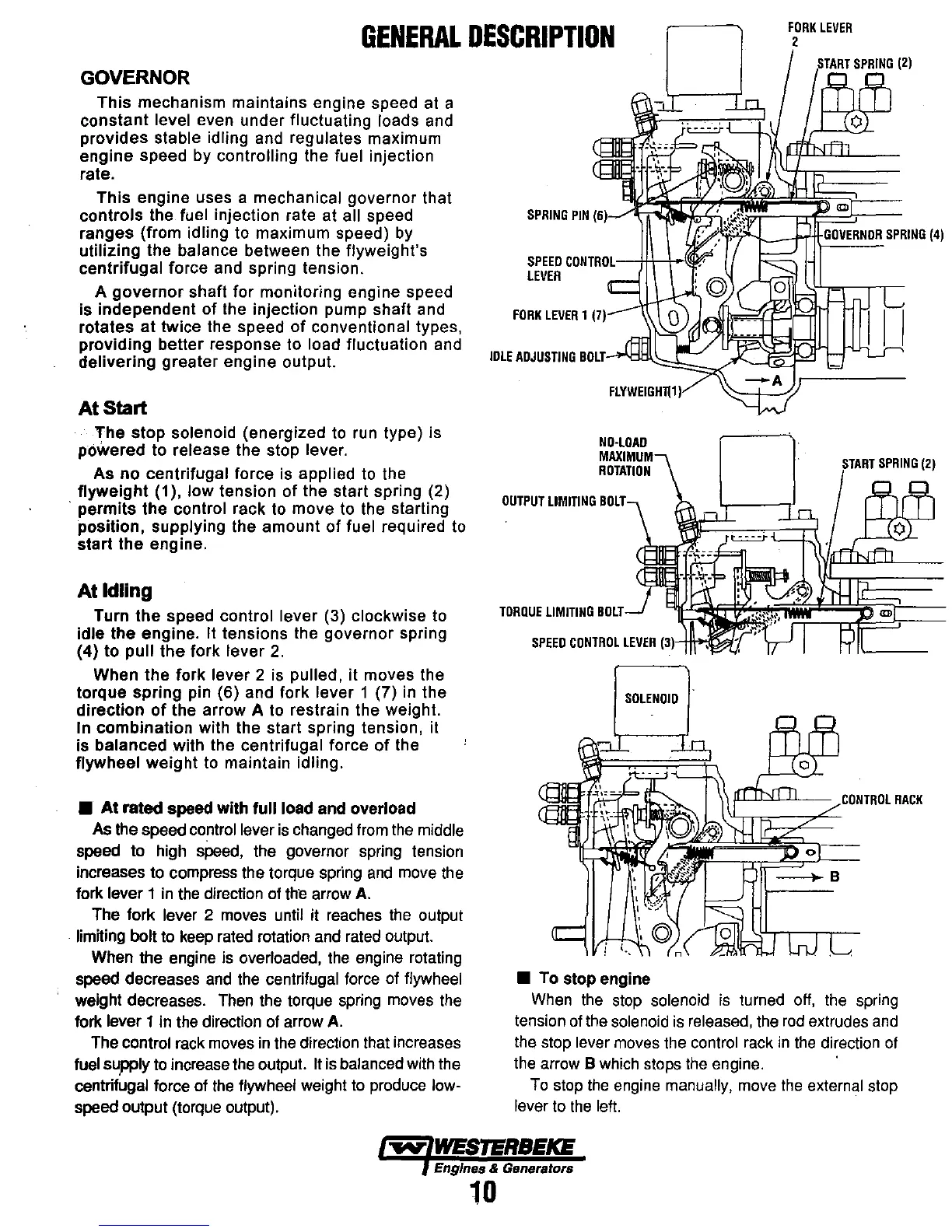
GOVERNOR
This
mechanism maintains engine speed at a
constant
level even under fluctuating loads and
provides
stable idling and regulates maximum
engine speed by
controlling the fuel injection
rate.
This
engine uses a mechanical governor that
controls the fuel injection rate at all speed
ranges (from
idling to maximum speed)
by
utilizing the balance between the flyweight's
centrifugal
force and spring tension.
A
governor
shaft for monitoring engine speed
is independent
of
the injection pump shaft and
rotates
at
twice the speed
of
conventional types,
providing better response to
load fluctuation and
delivering greater engine output.
At
Start
The
stop
solenoid (energized to run type) is
powered to
release the stop lever.
As no centrifugal force is applied to the
flyweight
(1), low tension
of
the start spring (2)
. permits the control rack to move to the starting
position,
supplying the amount
of
fuel required to
start
the
engine.
At
Idling
Turn
the
speed control lever (3) clockwise to
idle the engine. It tensions the governor spring
(4) to
pull
the
fork lever
2.
When the fork lever 2 is pulled, it moves the
torque spring pin (6) and fork
lever 1 (7)
in
the
direction
of
the arrow A to restrain the weight.
In combination with the start spring tension, it
is
balanced with the centrifugal force
of
the
flywheel
weight
to maintain idling.
• At rated speed with full load and overload
As
the speed control lever
is
changed
from
the
middle
speed to high
speed,
the governor spring tension
increases to compress the torque spring
and
move
the
fork lever 1
in
the
direction
of
the
arrow
A.
The fork lever 2
moves
until it
reaches
the
output
limiting bolt
to
keep
rated
rotation
and
rated
output.
When the engine
is
overloaded,
the
engine rotating
speed decreases
and
the
centrifugal force of flywheel
weight decreases.
Then
the torque
spring
moves
the
fork lever 1
in
the
direction
of
arrow
A.
The control
rack
moves
in
the
direction that increases
fuel supply
to
increase
the
output.
It
is
balanced with the
centrifugal force of
the
flywheel weight
to
produce low-
speed output (torque output).
SPRING
PIN
(6)';~~~~Q\;;;;~-.T'J'!:="'5---
SPEEO
CONTROL--ttt+~r
LEVER
FORK
LEVER
1
(7)
IDLE
ADJUSTING
BOLT-'Oll~::h;",,<
FLYWEIGH1l1
)
NO·LOAD
ROTATION
OUTPUT
LIMITING
BOLT
TORQUE
LIMITING
BOLT
SPEEO
CONTROL
LEVER
131-H\+l
• To stop engine
GOVERNOR
SPRING
(4)
/ll-l.l..>..w.J--
CONTROL
RACK
When
the
stop
solenoid
is
turned
off,
the
spring
tension
of
the
solenoid
is
released,
the
rod
extrudes
and
the stop lever
moves
the control
rack
in
the
direction
of
the
arrow B
which
stops
the
engine.
To
stop
the
engine
manually,
move
the
external stop
lever
to
the
left.
'9Y'
WESTERBEKE
Engines & Generators
10