DISASSEMBLY/ASSEMBLY
Gear Case
Gear Case Cover
1.
Remove the gear case cover.
(When reassembling)
• Confirm that the liquid gasket coating surface
is
free
of
water,
dust and
oil in order to maintain sealing effect.
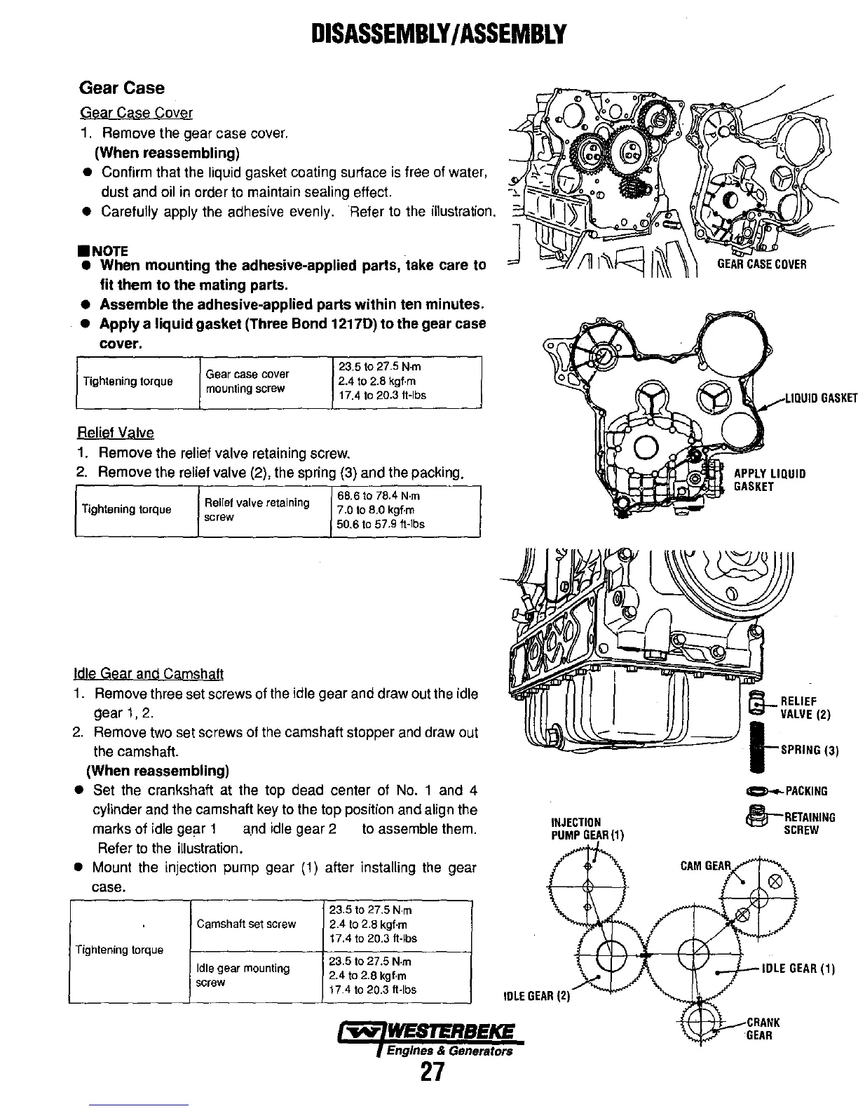
• Carefully apply the adhesive evenly. Refer to the illustration .
•
NOTE
• When mounting the adhesive-applied parts, take care to
fit
them
to
the mating parts.
• Assemble the adhesive-applied parts within ten minutes.
• Apply a liquid gasket (Three Bond 12170) to the gear case
cover.
Gear
case
cover
23.5
to
27.5
N·m
Tightening torque
mounting screw
2.4
to
2.8
kgf·m
17.4
to
20.3 h-Ibs
Relief Valve
1.
Remove the relief valve retaining screw.
2.
Remove the relief valve (2), the spring (3) and the packing.
Relief valve retaining
68.6
to
78.4
N·m
Tightening torque
7.0
to
B.O
kgf·m
screw
50.6
to
57.9 h-Ibs
Idle Gear and Camshaft
1.
Remove three set screws of the idle gear and draw out the idle
gear
1,
2.
2.
Remove two set screws of the camshaft stopper
and
draw out
the camshaft.
(When reassembling)
• Set the crankshaft at the top dead center of
No.
1 and 4
cylinder and the camshaft key to the top position and align the
marks of
idle gear 1
a.nd
idle gear 2
to
assemble them.
Refer
to
the illustration .
• Mount the injection pump gear
(1)
after installing the gear
case.
23.5
to
27.5
N·m
CamShaft
set screw
2.4
to
2.8
kgf·m
17.4
to
20.3 h-Ibs
Tightening torque
Idle
gear mounting
23.5
to
27.5
N·m
2.4
to
2.8
kgf·m
screw
17.4
to
20.3 «-Ibs
"""
WESTERBEKE
Engines & Generators
27
INJECTION
PUMP
GEAR
(1)
,/,LIUIUIU
GASKET
~
RELIEF
~VALVE
(2)
!-SPRING
(3)
~PACKING
§-RETAINING
SCREW
..-i...-IDLE
GEAR
(1)
CRANK
'GEAR