SERVICING
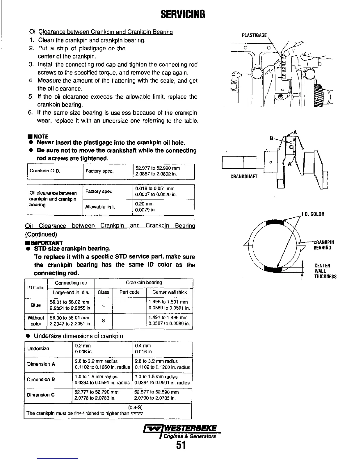
Oil Clearance between Crankpin and Crankpin Bearing
1.
Clean
the
crankpin
and
crankpin bearing.
2.
Put a strip of plastigage
on
the
center of the crankpin.
3. Install the connecting
rod
cap and tighten the connecting
rod
screws to
the
specified torque, and remove the
cap
again.
4. Measure the amount
of
the
flattening with
the
scale,
and
get
the oil clearance.
5. If the oil clearance exceeds the allowable limit, replace the
crankpin bearing.
6. If the same size bearing
is
useless because of the crankpin
wear, replace it with
an
undersize one referring
to
the
table .
•
NOTE
•
Never
insert
the
plastigage
into
the
crankpin oil hole.
•
Be
sure
not
to
move
the
crankshaft while
the
connecting
rod
screws
are tightened.
Crankpin
0.0.
Factory spec.
52.977
to
52.990
mm
2.0857 to 2.0862
in.
Factory spec.
0.018
to
0.051
mm
Oil clearance between
0.0007
to
0.0020
in.
crankpin and crankpln
bearing
Allowable limit
0.20
mm
0.0079 in.
Oil Clearance between Crankpin
and
Crankpin Bearing
(Continued)
•
IMPORTANT
• STD
size
crankpin
bearing.
To
replace
it
with
a specific STD service part, make sure
the
crankpin
bearing has
the
same
ID
color
as
the
connecting
rod.
Connecting
rod
Crankpin bearing
10
Color
Large-end in. dia.
Class
Part code
Center
wall thick
Blue
56.01 to 56.02
mm
L
1.496
to
1.501
mm
2.2051 to 2.2055
in.
0.0589
to
0.0591
in.
Without 56.00 to
56.Q1
mm
S
1.491
to 1.496
mm
color 2.2047 to
2.2051
in.
0.0587 to 0.0589 in.
• Undersize dimensions of crankpin
Undersize
O.2mm 0.4
mm
0.008 in.
0.Q16
in.
Dimension A
2.8
to 3.2
mm
radius 2.8
to
3.2
mm
radius
0.1102 to 0.1260
in.
radius 0.1102 to 0.1260
in.
radius
Dimension B
1.0
to
1.5
mm
radius
1.0
to 1.5 mm radius
0.0394 to
0.0591
in. radius 0.0394
to
0.0591
in.
radius
Dimension C
52.777 to 52.790
mm
52.577 to 52.590
mm
2.077810 2.0783
In.
2.07DO
to 2.0705
in.
(0.8·S)
The
crankpin must be fintl-fjl'Jished to higher than
vvvv
~
WESTERBEKE
Engines & Generators
51
PlASTIGAGE
B
a
CRANKSHAFT
o
1.0.
COLOR
CRANKPIN
BEARING
CENTER
WAll
THICKNESS