DISASSEMBLY
I
ASSEMBLY
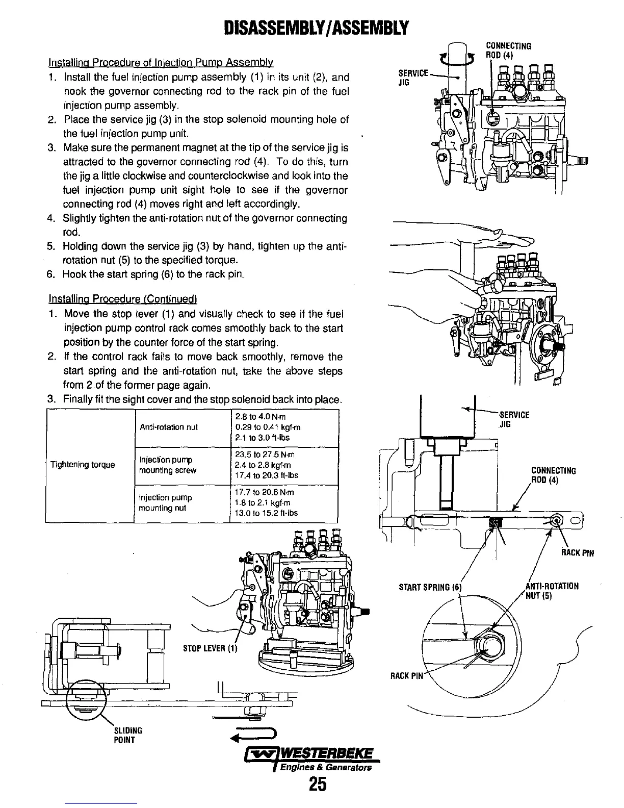
Installing Procedure of Injection Pump Assembly
1.
Install the fuel injection pump assembly (1) in its unit
(2),
and
hook the governor connecting rod to the rack pin
of
the fuel
injection pump assembly.
2.
Place the service jig
(3)
in
the stop solenoid mounting hole of
the
fuel injection pump unit.
3.
Make sure the permanent magnet at the tip of the service jig is
attracted to the governor connecting rod (4). To do this, turn
the jig a
little clockwise and counterclockwise and look into the
fuel injection pump unit sight hole to see if the governor
connecting
rod
(4)
moves right and left accordingly.
4.
Slightly tighten the anti-rotation nut of the governor connecting
rod.
5.
Holding down the service jig (3) by hand, tighten up the anti-
rotation nut
(5)
to
the specified torque.
6.
Hook the start spring
(6)
to the rack
pin.
Installing Procedure (Continued I
1.
Move the stop lever
(1)
and visually check
to
see
if the fuel
injection pump control rack comes smoothly back
to
the start
position by the counter force of the start spring.
2.
If the control rack fails to move back smoothly, remove the
start spring and the anti-rotation
nut,
take the above steps
from 2 of the former page again.
3.
Finally fit the sight cover and the stop solenoid back into place.
2.8 to 4.0
N·m
Tightening
torque
Anti-rotation
nut
Injection
pump
mounting
screw
Injection
pump
mounting
nut
SLIDING
POINT
0.29 to 0.41 kgf·m
2.1
to 3.0 ft·lbs
23.5 to 27.5
N·m
2.4 to 2.8 kgf·m
17.4 to 20.3 ft-Ibs
17.7 to 20.6
N·m
1.8 to
2.1
kgf·m
13.0
to 15.2 ft·lbs
)
Engines & Generators
25
START
SPRING
RACK
PIN
JIG
CONNECTING
(4)
(5)