ELECTRONIC
REGULATION
SR7-2G
AVR
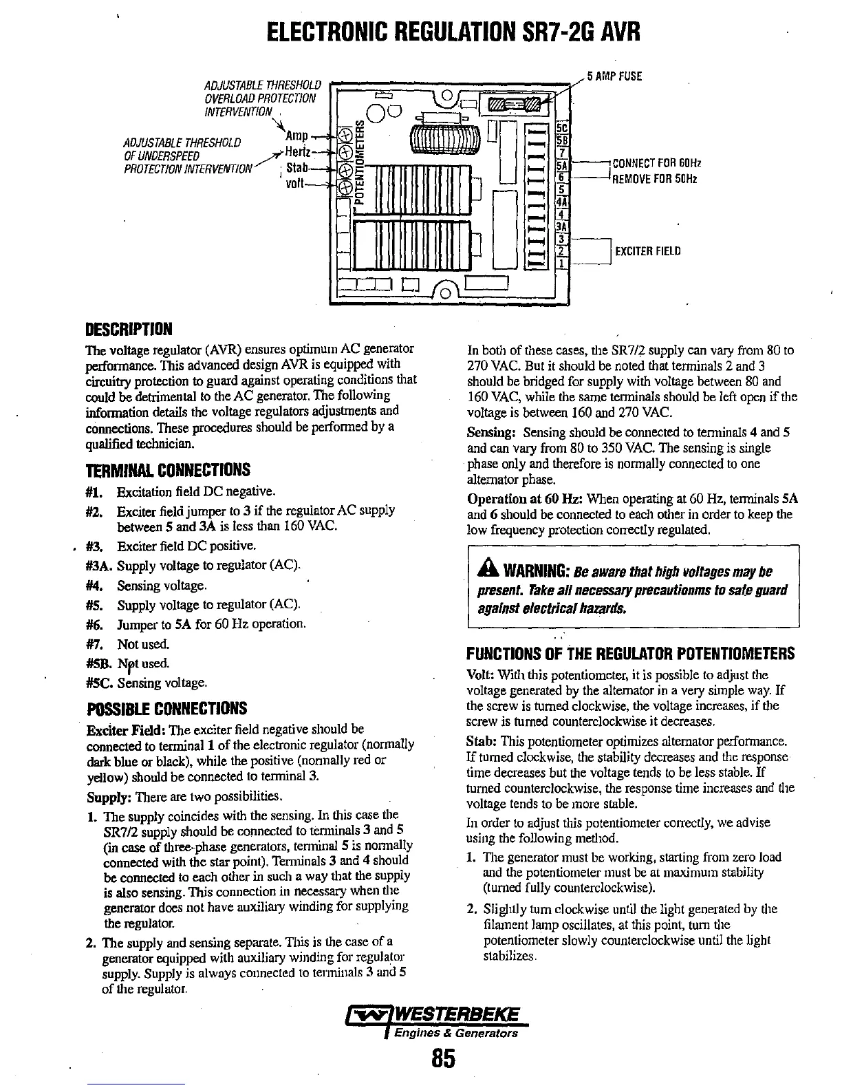
ADJUSTABLE
THRESHOLD
OVERLOAD
PROTECTION
AMP
FUSE
ADJUSTABLE
THRESHOLD
OF
UNDERSPEED
PROTECTION
INTERVENTION
""Hertz--,'jo~(-\-):E°O
..
DO
1;!a1--tCDI~NEICT
FOR
60Hz
rn---l
REMOVE
FOR
50Hz
o
DESCRIPTION
The
voltage regulator
(AVR)
ensures
optimum
AC
generator
performance.
TIlis
advanced
design
AVR
is
equipped
with
circuitry protection to guard against operating conditions
tllat
could
be detrimental
to
the
AC
generator.
The following
information details
the
voltage regulators adjustments
and
connections.
These
procedures should
be
performed
by
a
qualified technician.
TERMINAL
CONNECTIONS
#1.
Excitation
field
DC negative.
#2.
Exciter
field
jumper
to
3 if
the
regulator
AC
supply
between S and
3A
is
less
than
160
VAC.
#3.
Exciter
field
DC positive.
#3A.
Supply voltage
to
regulator (Ae).
#4.
Sensing voltage.
#5.
Supply voltage
to
regulator (Ae).
#6.
Jumper
to
SA
for
60
Hz
operation.
#7.
Not
used.
#5B.
Npt
used.
#5C. Sensing
voltage.
POSSIBLE
CONNECTIONS
Exciter Field: The exciter
field
negative should
be
connected
to
terminal 1 of the electronic regulator
(normally
dark
blue
or
black), while
the
positive (nonnally
red
or
yellow)
should be connected
to
terminal
3.
Supply: There
are
two
possibilities.
1.
The supply coincides
with
the
sensing.
In
tllis
case
the
SR712
supply should
be
connected
to
tenninals 3
and
S
(in case of three-phase generators,
terminal
S
is
normally
connected
Witll
the star point). Ternnnals 3
and
4
should
be
connected
to
each otller
in
such
a
way
that
the
supply
is
also sensing. This connection
in
necessary
when
the
generator
does
1I0t
have auxiliary
winding
for supplying
the
regulator.
2.
The supply
and
sensing separate. Tins
is
the
case of a
generator equipped
with
auxiliary winding
for
regulator
supply.
Supply
is
always connected
to
terminals
3
and
5
of the
regulator.
o
EXCITER
FIELD
In
both
of
these
cases,
tlle
SR7/2
supply
can
vary
from
80
to
270
VAC.
But
it
should be
noted
that terminals 2
and
3
should be bridged for supply
with
voltage
between
80
and
160
VAC,
while
the
same
terminals
should
be
left
open
if
the
voltage
is
between
160
and
270
VAC.
Sensing: Sensing should
be
connected
to
terminals
4
and
S
and
can
vary
from
80
to
350
VAC.
The
sensing
is
single
phase
only
and
therefore
is
normally
connected
to
one
alternator
phase.
Operation
at
60
Hz:
When
operating
at
60
Hz,
terminals
SA
and
6 should
be
connected
to
each
other
in
order
to
keep
tlle
low
frequency protection correctly regulated.
A
WARNING:
Be
aware
that
high
voltages
may
be
present.
Take
all
necessary
precautionms
to
safe
guard
against
electrical
hazards.
FUNCTIONS
OF
THE
REGULATOR
POTENTIOMETERS
Volt:
Witll
this potentiometer, it
is
possible
to
adjust
the
voltage generated
by
the alternator
in
a
very
simple
way.
If
the
screw
is
tumed clockwise,
the
voltage
increases,
if
tlle
screw
is
turned
counterclockwise it
decreases.
Stab:
This
potentiometer optinlizes altemator
performance.
If
turned
clockwise,
the
stability
decreases
and
the
response
time
decreases but
the
voltage
tends
to
be
less
stable.
If
turned
cOllnterclockwise,
the
response
time
increases
and
the
voltage
tends
to
be
more
stable.
In
order
to
adjust
tlIis
potentiometer
cOlTectly,
we
advise
using
the
following
metllod.
1.
The generator
must
be
working,
starting
frolll
zero
load
and the potentiometer must be at
maximum
stability
(turned
fully
counterclockwise).
2.
Slightly
tum
clockwise
until
tlle
light
generated
by
tlle
filament
lamp
oscillates,
at
this
point,
tUIll
tlle
potentiometer
slowly
counterclockwise
until
tlle
light
stabilizes.
Engines & Generators
85