ELECTRONIC
REGULATION
SR7-2G
AVR
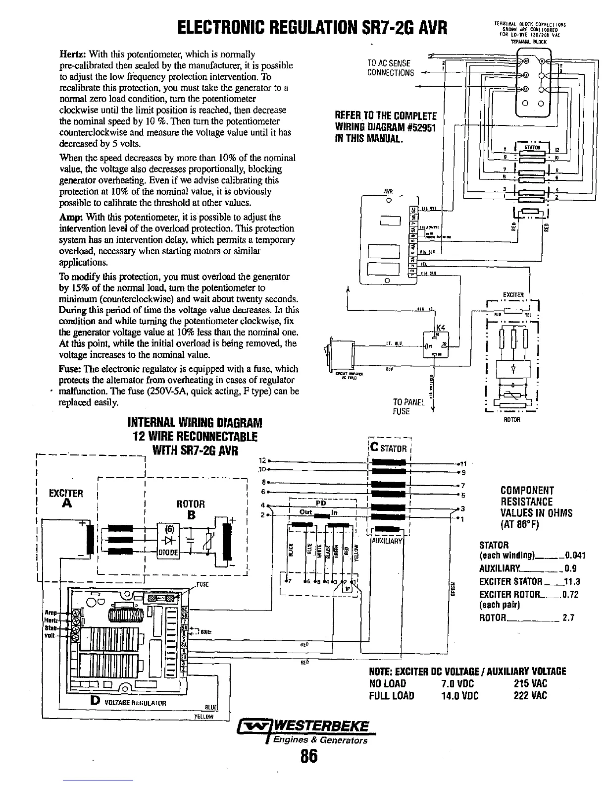
Hertz:
With
this
potentiometer,
which
is
normally
pre-calibrated
then
sealed
by
the
manufacturer,
it
is
possible
to
adjust
the
low
frequency
protection intervention.
To
recalibrate this protection. you must take the generator
to
a
nonnal zero load condition, tum the potentiometer
clockwise
until
the
limit
position
is
reached,
then
decrease
the
nominal
speed
by
10
%.
Then
turn
the potentiometer
counterclockwise
and
measure
the
voltage
value
until
it
has
decreased
by
5
volts.
When
the
speed
decreases
by
more
than
10%
of
the
nominal
value,
the
voltage
also
decreases proportionally,
blocking
generator overheating.
Even
if
we
advise
calibrating
this
protection
at
10%
of
the
nominal
value,
it
is
obviously
possible
to
calibrate the threshold
at
other
values.
Amp:
With
this
potentiometer,
it
is
possible
to
adjust
the
intervention level of
the
overload protection. This protection
system
has
an
intervention
delay,
which
permits a
temporary
overload, necessary
when
starting
motors
or
similar
applications.
,
TO
AC
SENSE
,
CONNECTIONS
REFER
TO
THE
COMPLETE
WIRING
DIAGRAM
#52951
IN
THIS
MANUAL.
AVR
0
"
'
.,
CJ
•
"
"p;!lm!
:
::..
..
..
I
I
-:
I'
Itl
•
I
I
" '
: _
...
'"'-
0
t
, ,
To
modify
this
protection,
you
must
overload the generator
by
15%
of
the
normal
load,
turn
the
potentiometer
to
minimum (counterclockwise)
and
wait about
twenty
seconds.
During this period
of
time
the
voltage
value
decreases.
In
this
condition
and
while
turning
the
potentiometer clockwise,
fix
the
generator voltage value
at
10%
less
than
the
nominal
one.
At
this
point,
while
the
initial overload
is
being
removed,
the
voltage increases
to
the
nominal
value.
1f-
c3-
II.
SlU
G·
Fuse: The electronic regulator
is
equipped
with
a
fuse,
which
protects
the
alternator
from
overheating in
cases
of regulator
malfunction. The
fuse
(250V-5A,
quick acting, F
type)
can
be
replaoed
easily.
INTERNAL
WIRING
DIAGRAM
12
WIRE
RECDNNECTABLE
--
....
".
TO
PANEL
FUSE
~"""'-----,
I 1 " r i
I
r-~-
-.!
_________
_
8
6
I I r
"I
I
EXCITER
I I 1
I A I I
ROTOR
r
: I : B
r-+
i '
I
-rl"
,'(6)
I'
r
I
ill
-i>/-J.
J!
I
I i I I
DIODE
_T
~
r
I - I I
'--
I I I
I L I
L-
-
I.
L
---r-----
-----...1
-
~
.~mp
,IL..'
~
0 F
~~'"
IlIlllllWUIJ
1=
:,':1111
p
I~
~~------;;,,,m--J--lJ
,---
'--
·f-
,
9
T(Rl(IHAl
aLOCK
CO~N(CTIONS
SMOWH
AR(
COHrlGUR[O
fOR
lO·'H
t~OHoa
VAt
_-.oc,
~
,
.
,
,
,
0
0
n
I~T~~--'
12
,
..
7
I ,
5
- ,
:
1_5~
4
~~i
~
EXCITER
r"-"
l
•
eli
TEL-
~
.~
-;:--:
.
-;
I
I
:
I
¥
I
I
~I
'-
..
..
ROTOR
COMPONENT
RESISTANCE
VALUES
IN
OHMS
(AT
86'F)
STATOR
(each
wlndlng)
___
0.041
AUXIlIARY.
____
0.9
EXCITER
STATOR_ll.3
EXCITER
ROTOR
__
.
O.
72
(each
pair)
ROTOR
__
_
2.7
III
hO
~
~=~======i==,,,=--
__
-'--===T-------.J
III
W::::
NOTE:
EXCITER
DC
VOLTAGE
I
AUXILIARY
VOLTAGE
o
In\c::=J
NO
LOAO
7.0
VUC
215
VAC
D
VOLTAGE
RmULATOR
'WE
YEllOW
FULllOAU
14.0
VUC
222
VAC
,
"",",WESTERBEKE
,
Engines
&
Generators
86