DISASSEMBLY
I
ASSEMBLY
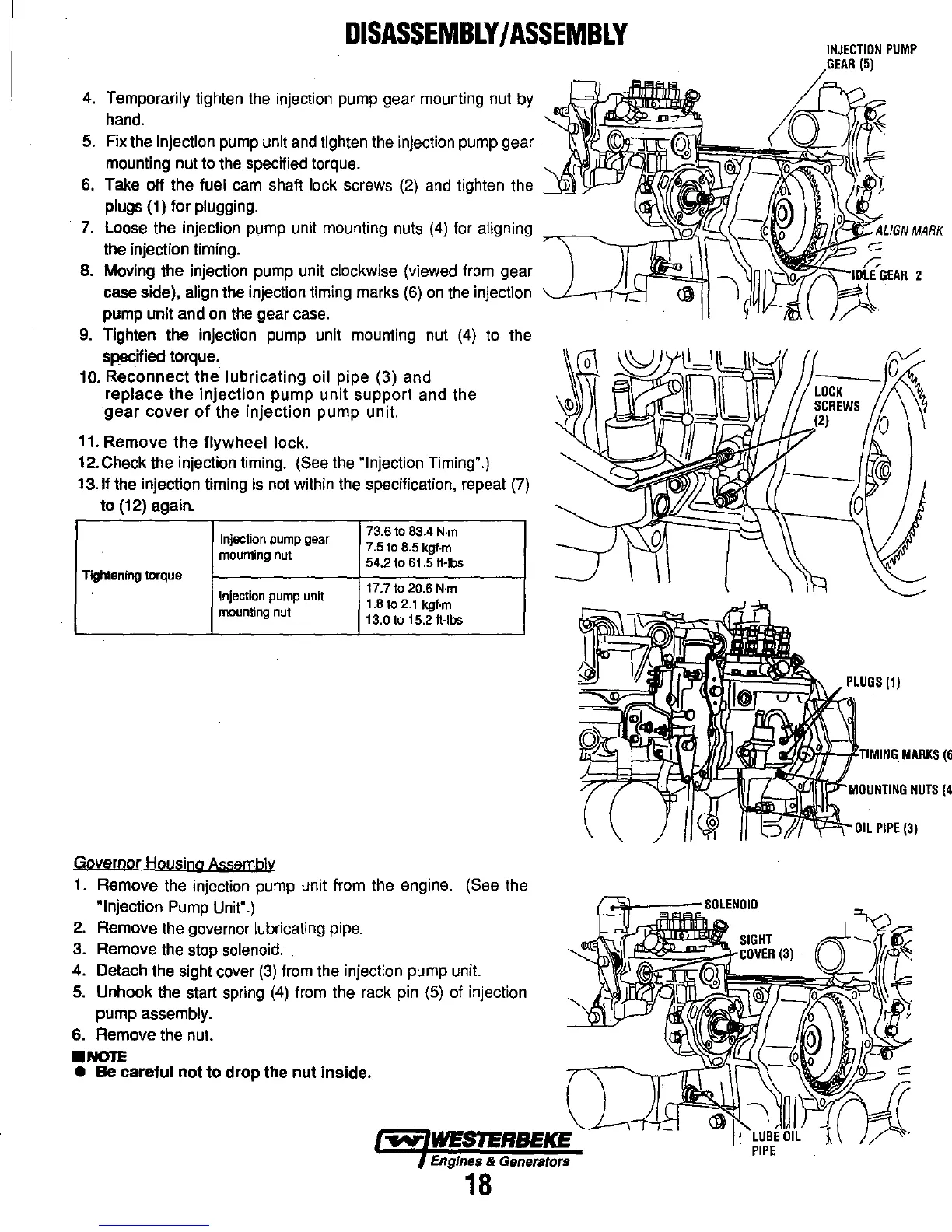
4.
Temporarily tighten the injection pump gear mounting nut
by
hand.
5.
Fix the injection pump unit
and
tighten the injection pump gear
mounting nut to the specified torque.
S.
Take off the fuel
cam
shaft lock screws
(2)
and
tighten the
---""-'
plugs (1) for plugging.
INJECTION
PUMP
GEAR
(5)
7.
Loose the injection pump unit mounting nuts
(4)
for aligning
,....-<,----.~_...,.,..,.u"'1
the injection timing.
8. Moving the injection pump unit clockwise (viewed from gear
case side), align the injection timing marks
(S)
on
the
injection
pump unit and
on
the
gear
case.
9.
Tighten the injection pump unit mounting nut
(4)
to the
specified torque.
10.
Reconnect
the lubricating oil pipe (3) and
replace
the
injection pump
unit
support and the
gear
cover
of
the injection pump unit.
11.
Remove
the flywheel lock.
12. Check the injection timing. (See the "Injection Timing".)
13.lf the injection timing is
not
within the specification, repeat
(7)
to (12) again.
Injection
pump
gear
73.6 to 83.4
N·m
7.5 to 8.5 kgf·m
mounting
nut
54.2 to
6t.5
h-Ibs
TIghtening torque
Injection
pump
unit
17.7 to 20.6 N'm
t.8
to
2.1
kgf·m
mounting
nut
13.0 to 15.2 h-Ibs
Governor Housing Assembly
1. Remove the injection pump unit from the engine. (See the
"Injection Pump Unit".)
2.
Remove the governor lubricating pipe.
3. Remove the stop solenoid
..
4. Detach the sight cover
(3)
from the injection pump unit.
5.
Unhook the start spring
(4)
from the rack
pin
(5)
of injection
pump assembly.
S.
Remove the nut.
.NOTE
• Be careful
not
to
drop
the
nut
inside.
Engines & Generators
18
~~~
Jm}ctfil~:m=~TIIMINGIMARKS
(6
~~J.I.-:;\~
r--T~(ji'tl-MnolNTlINn
NUTS
(4