DISASSEMBLY
I
ASSEMBLY
Injection
Pump
Unit
(Removing the fuel injection
pump
unit)
1.
Detach
the
gear cover for
the
fuel injection
pump
unit
from
the
gearcase.
2.
Place
the
piston
of
the
4th
cylinder
at
the
top
dead
center
in
the
compression
stroke.
Lock the flywheel
in
place .
•
IMPORTANT
SUPPORT
~~~lF~U~~~~17t17):::""'PLUGS(l)
•
look
for
the align mark on the idle .gear
2.
Using a white
marking pen
or
the like, put
an
align mark on the engaged
tooth of the
idle gear. This helps to reassemble these
gears in mesh
later .
•
NOTE
• When the already existing align marks align with each
other, there
is
no need
to
put
another align mark.
3.
Unscrew
the
two
plugs
(1)
off
the injection pump
unit.
4.
Tighten
the
upper
fuel
cam
shaft lock screw
until
it
comes
into
contact with the
fuel
cam
shaft.
Make
sure the
cam
shaft
does
not
move
any
longer.
5.
Tighten the lower
fuel
cam
shaft lock screw
(2)
until
it
comes
into contact with
the
fuel
cam
shaft .
•
NOTE
• Never overtighten the lock screws when they have come
into contact with the cam shaft. Otherwise the injection
pump unit
itself may get damaged.
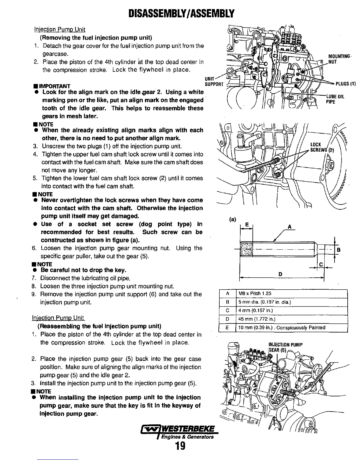
• Use
of
a socket set screw (dog point type) in
recommended for best
results. Such screw can be
constructed as shown in figure (a).
6.
loosen
the
injection
pump
gear mounting
nut.
Using
the
specific gear puller, take
out
the gear
(5)
.
•
NOTE
• Be careful
not
to
drop
the key.
7.
Disconnect
the
lubricating
oil
pipe.
8.
Loosen
the
three injection pump unit mounting
nut.
9.
Remove
the
injection pump unit support
(6)
and
take
out
the
injection pump unit.
Injection Pump Unit
(Reassembling the fuel injection pump unit)
1.
Place
the
piston
of
the
4th
cylinder
at
the
top
dead
center
in
the
compression
stroke.
Lock the flywheel
in
place.
2.
Place the injection
pump
gear
(5)
back into
the
gear
case
position.
Make
sure
of
aligning
the
align marks
of
the
injection
pump gear
(5)
and
the
idle
gear
2.
3.
install the injection
pump
unit
to
the injection
pump
gear
(5)
.
•
NOTE
• When installing the injection pump unit to the injection
pump
gear, make sure that the key
is
fit in the keyway
of
injection pump gear.
~
WESTERBEKE
Engines & Generators
19
(a)
-
~~~----
--1--
B
c
D
A M8 x Pilch 1.25
B
5 mm dia. (0. I
97
in. dia.)
C
4 mm (0.157 in.)
D 45 mm (1.772 in.)
E
10
mm
(0.39
in.)
: Conspicuously Painted