ALTERNATOR
SERVICE
DESCRIPTION
The stator is
connected
to
a three-phase,
full-wave
bridge
rectifier package
which
contains
six
diodes.
The bridge
converts the
AC
generated
in
the
stator
to
a
DC
output
for
battery charging
and
accessories,
Power
to the regulator
and
the
field
of
the
integral regulator
alternator
is
provided
by
the
field
diode
(or
diode trio)
package contained
in
the
alternator.
These alternators produce a rated output of
50
or
51
amps.
rated output
is
achieved
at
approximately 6000 alternator
!pm at
an
ambient temperature of 75'F (23.8'C). The
alternators are
designed
to
operate
in
an
ambient temperature
range of
-40'
to
212'F (-40'
to
lOO'C).
INSPECnDN
When
rebuilding
the
engine,
the
alternator
should
be
cleaned
and
inspected. The housing
can
be
wiped
off
with
a solvent
and
the alternator
temninal
studs should
be
cleaned
with
a
wire
brush.
Make
certain
the
studs
are
tight
and
clean
the
wiring connections that connect
to
the
wiring
harness.
Thm
the rotor
pulley
by
hand.
It
should tum
smoothly.
DISASSEMBLE
ALTERNATOR
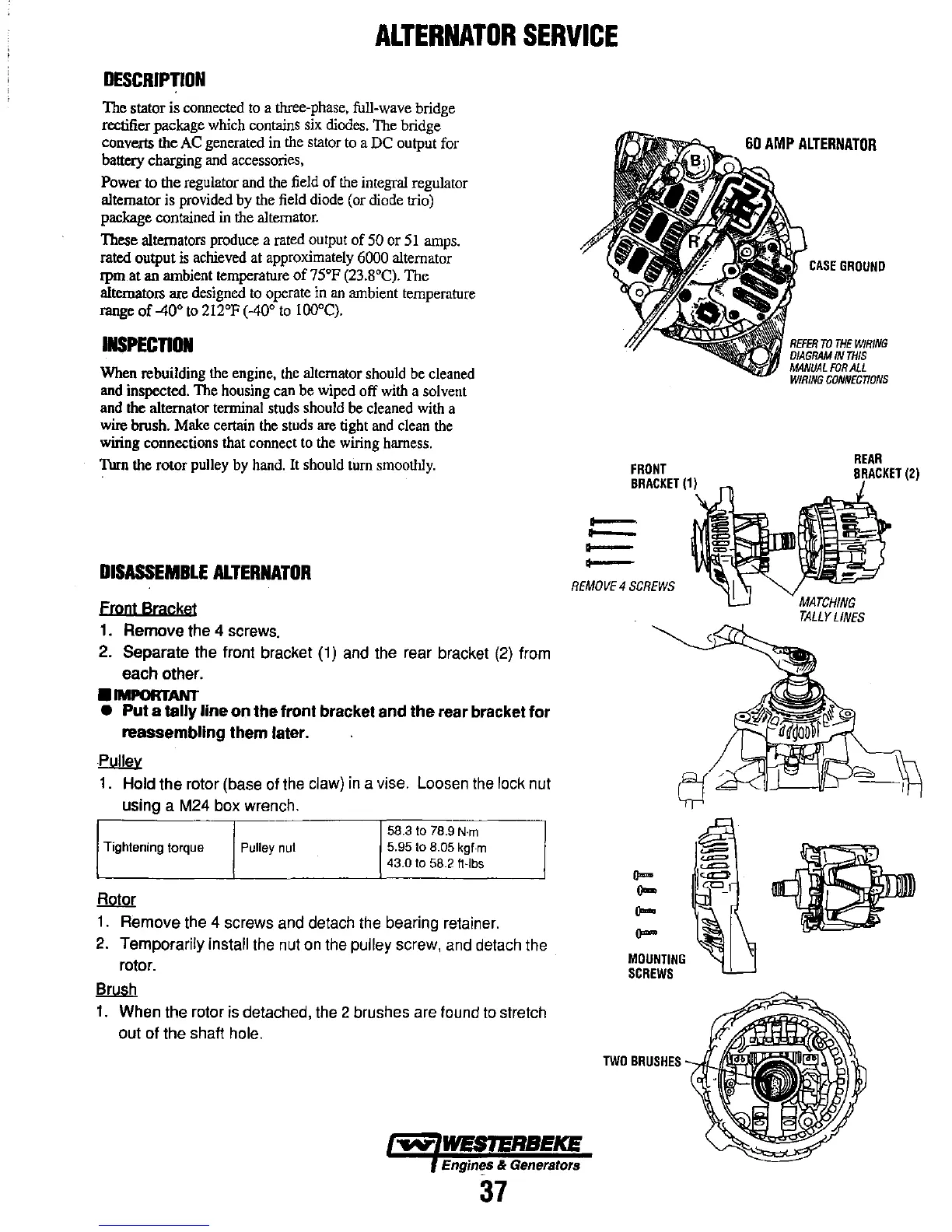
Front Bracket
1. Remove the 4 screws.
2.
Separate the fron! bracket (1) and the rear bracket
(2)
from
each other .
•
IMPORTANT
•
Put
a tally
line
on
the
front
bracket
and
the
rear bracket
for
reassembling
them
later.
Pulley
1.
Hold the rotor (base of the claw)
in
a vise. Loosen the lock nut
using a M24 box wrench.
58.3
to
78.9
N·m
Tightening torque Pulley nul 5.95
to
8.05 kgf·m
43.0
to
58.2 ft·lbs
Rotor
1.
Remove the 4 screws and detach the bearing retainer.
2. Temporarily install the nut
on
the pulley screw, and detach the
rotor.
Brush
1.
When the rotor is detached, the 2 brushes are found
to
stretch
out of the shaft hole.
FRONT
BRACKET
(1)
--
-
--
-
REMOVE
4
SCREWS
0-
0-
0-
0-
MOUNTING
SCREWS
TWO
BRUSHES
Engin'!.s & Generators
37
60
AMP
ALTERNATOR
CASE
GROUND
REFER
TO
THE
WIRING
DIAGRAM
IN
THIS
MANUAL
FOR
ALL
WIRING
CONNECnONS
REAR
BRACKET
(2)