DISASSEMBLY
I
ASSEMBLY
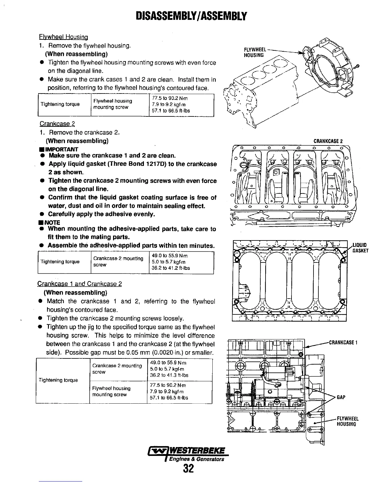
Flywheel Housing
1.
Remove
the
flywheel housing.
(When
reassembling)
•
Tighten
the
flywheel housing mounting screws with
even
force
on
the diagonal line.
• Make sure
the
crank cases 1
and
2 are clean. Install them
in
position, referring
to
the flywheel housing's contoured face.
Flywheel housing
77.5
to
90.2
N·m
Tightening torque
mounting screw
7.9
to
9.2
kgf·m
57.1
to
66.5 «·Ibs
Crankcase 2
1.
Remove the crankcase 2.
(When reassembling)
•
IMPORTANT
• Make sure
the
crankcase 1 and 2 are clean.
•
Apply
liquid
gasket (Three
Bond
12170)
to
the crankcase
2
as
shown.
•
Tighten
the crankcase 2
mounting
screws
with
even
force
on
the
diagonal line.
•
Confirm
that the
liquid
gasket coating surface is free
of
water,
dust
and oil
in
order
to maintain sealing effect.
• Carefully
apply
the
adhesive evenly.
•
NOTE
• When
mounting
the
adhesive-applied parts, take care to
fit
them
to the mating parts.
• Assemble the adhesive-applied parts
within
ten minutes.
Crankcase 2 mounting
Tightening torque
screw
Crankcase 1 and Crankcase 2
(When
reassembling)
49.0
to
55.9
N·m
5.0
to
5.7 kgf·m
36.2
to
41.2 «·Ibs
• Match the crankcase 1
and
2,
referring
to
the
flywheel
housing's contoured face.
• Tighten the crankcase 2 mounting screws loosely.
• Tighten
up
the jig to the specified torque same
as
the
flywheel
housing screw. This helps
to
minimize
the
level difference
between
the
crankcase 1
and
the
crankcase 2 (at
the
flywheel
side). Possible gap must
be
0.05
mm
(0.0020
in.)
or smaller.
Crankcase 2 mounting
49.0
to
55.9
N·m
5.0
to
5.7 kgf·m
screw
36.2
to
41.3 It·lbs
Tightening torque
Flywheel housing
77.5
to
90.2
N·m
7.9
to
9.2
kgf·m
mounting screw
57.1
to
66.5 ft·lbs
~
WESTERBEKE
Engines & Generators
32
[/0
0
0 0
°
SIT
'1
/~
~
o
Sil
}(r9J
~
1=
'fA,-
0
0
f-
°
fir
1\
l=
•
0
0
0 0
~
co:,":::>
,
,
~
CRANKCASE
2
,0
0
0
0"l
;J
\..
/
\..0
~
,
~]
0
)(,
f-n
0
1-
U~
-
b
)
0
0 0
Jf~
)(
~-'O\_.
0
0
i5'J
.<.J J
CRANKCASE
1
GAP
FLYWHEEL
HOUSING