DISASSEMBLY
I
ASSEMBLY
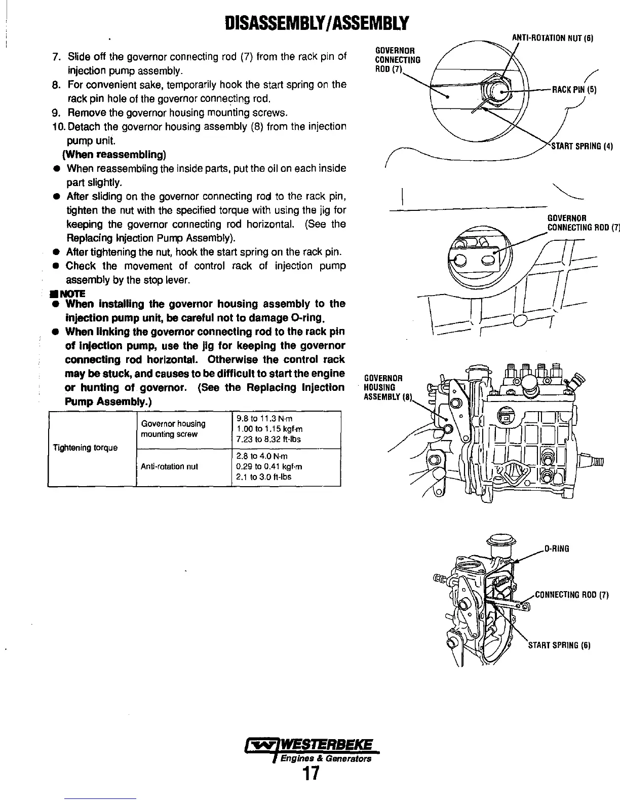
7. Slide off the governor connecting
rod
(7) from the rack pin of
injection pump
assembly.
GOVERNOR
CONNECTING
ROD
(7)
8. For convenient sake, temporarily hook the start spring
on
the
rack pin
hole of the governor connecting rod.
/
~;o-===ffFt':~-Hr--RACK
PIN
(51
9. Remove the governor housing mounting screws.
10.
Detach the governor housing assembly (8) from the injection
pump unit.
(When reassembling)
• When reassembling the inside parts, put the oil
on
each inside
part
slightly.
•
After sliding on the governor connecting
roa
to the rack pin,
tighten the nut with the specified torque with using the jig for
keeping the governor connecting
rod
horizontal. (See the
Replacing Injection
Pump
Assembly).
•
After tightening the
nut,
hook the start spring on the rack pin.
• Check the movement of control rack of injection pump
assembly by the stop lever .
•
NOTE
• When installing the governor housing assembly to the
injection pump unit,
be careful not to damage O.ring.
•
When linking the governor connecting rod to the rack pin
of injection pump, use the jig for keeping the governor
connecting rod
horizontal. Otherwise the control rack
may
be stuck, and causes
to
be difficult to start the engine
or hunting of governor.
(See the Replacing Injection
Pump Assembly.)
Governor
housing
9.B
to
11.3
N·m
1.00
to
1.15 kgf·m
mounting
screw
7.23
to
B.32 ft·lbs
Tightening
torque
2.B
to
4.0
N·m
Anti-rotation
nut
0.29
to
0.41
kgf·m
2.1
to
3.0 ft·lbs
GOVERNOR
HOUSING
ASSEMBLY
(81
Engines & Generators
17
1...".,'1
GOVERNOR
CONNECTING
ROD
(71
O·RING
'%;))
~0f~~~
CONNECTING
ROD
(7)
START
SPRING
(6)