DISASSEMBLY
I
ASSEMBLY
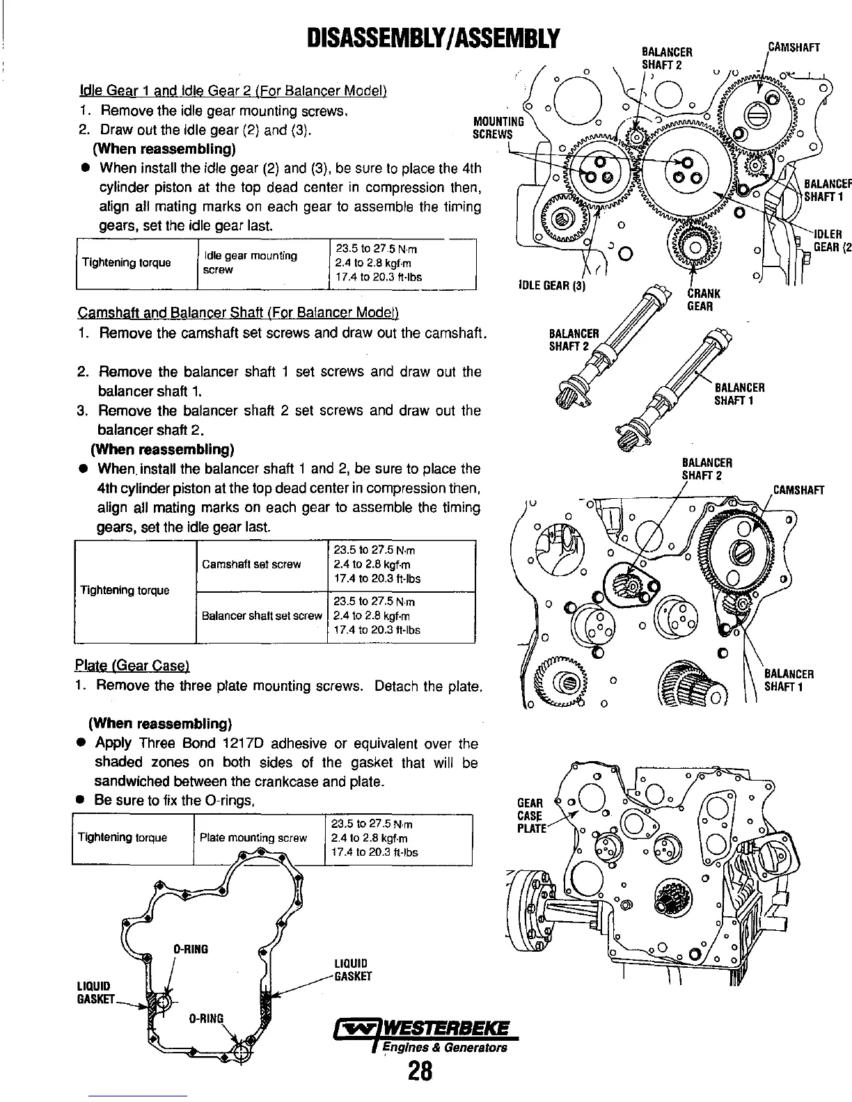
Idle Gear 1 and Idle Gear 2 (For Balancer Modell
1.
Remove the idle gear mounting screws.
2. Draw out the idle gear (2) and (3).
(When
reassembling)
o
MOUNTING
SCREWS
• When install the idle gear
(2)
and
(3),
be
sure
to
place the 4th
cylinder piston at the top dead center
in
compression then,
align all mating marks
on
each gear
to
assemble the
tifTling
gears, set the idle gear last.
Tightening
torque
Idle
gear
mounting
screw
23.5 to 27.5
N·m
~
2.4 to 2.8 kgf·m
17.4 to 20.3 ft·lbs
Camshaft and Balancer Shaft (For Balancer Model)
1.
Remove the camshaft set screws and draw out the camshaft.
2.
Remove the balancer shaft 1 set screws and draw out the
balancer shaft
1.
3.
Remove the balancer shaft 2 set screws and draw out the
balancer shaft
2.
(When
reassembling)
• When. install the balancer shaft 1 and
2,
be sure to place the
4th
cylinder piston at the top dead center
in
compression then,
align all mating marks on each gear to assemble the timing
gears, set the
idle gear last.
23.5 to 27.5
N·m
Camshaft
set
screw
2.4 to 2.8 kgf·m
17.4 to 20.3 ft·lbs
Tightening
torque
23.5 to 27.5
N·m
Balancer
shaft
set
screw
2.4 to 2.8 kgf·m
17.4 to 20.3 It·lbs
Plate (Gear Case)
1.
Remove the three plate mounting screws. Detach the plate.
(When
reassembling)
• Apply Three Bond 12170 adhesive or equivalent over the
shaded zones
on
both sides of the gasket that will be
sandwiched between the crankcase and
plate.
•
Be sure to fix the O-rings.
23.5 to 27.5
N·m
Tightening
torque
Plate
mounting
screw
2.4
to
2.8
kgf·m
LIQUID
GASKET
17.4 to 20.3 ft·lbs
LIQUID
GASKET
I!ngfnes & Generators
28
v
o
o
GEAR
CASE
PLATE
o
o
CRANK
GEAR
BALANCER
SHAFT
1
BALANCER
2
CAMSHAFT