DISASSEMBLY
I
ASSEMBLY
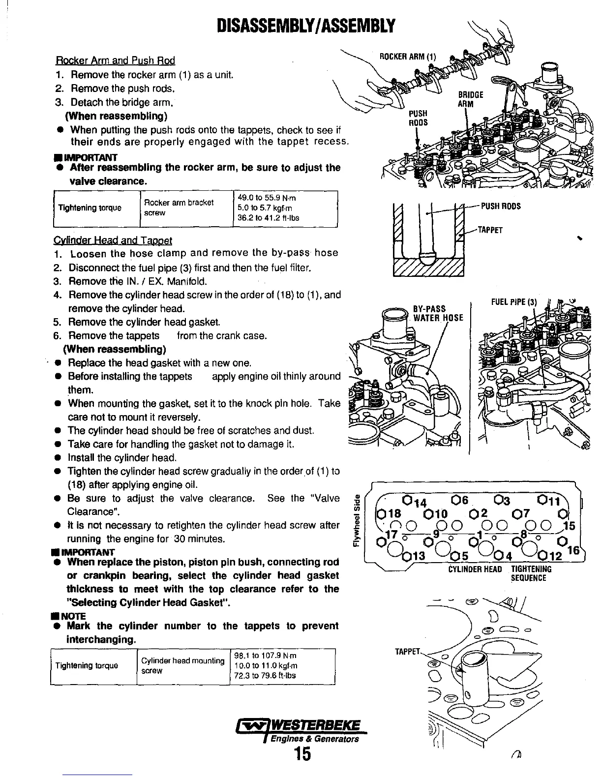
Rocker Arm
and
Push
Rod
1. Remove
the
rocker arm
(1)
as
a unit.
2. Remove
the
push rods.
3. Detach the bridge arm.
(When
reassembling)
•
When putting the push
rods
onto
the tappets, check
to
see if
their
ends are properly engaged with the
tappet
recess .
•
IMPORTANT
•
After
reassembling the rocker arm, be sure
to
adjust the
valve
clearance.
Rocker
arm
bracket
49.0 to 55.9
N·m
Tightening torque 5.0 to 5.7 kgf·m
screw
36.2 to 41.2 ft-Ibs
.
Cyfinder Head and Tappet
1.
Loosen the hose clamp and remove the by-pass hose
2.
Disconnect the fuel pipe
(3)
first
and
then the
fuel
filter.
3.
Remove ttie
IN.
/
EX.
Manifold.
4. Remove the cylinder head screw
in
the order
of
(18)
to
(1),
and
remove the cylinder head.
5.
Remove the cylinder
head
gasket.
6.
Remove the tappets from the crank case.
(When
reassembling)
• Replace
the head gasket
with
a new
one.
• Before installing the tappets apply engine oil thinly around
them.
• When mounting the gasket, set it
to
the knock
pin
hole.
Take
care not to mount it
reversely.
•
The cylinder head should
be
free of scratches
and
dust.
• Take care for handling the gasket not to damage
it.
• Install the cylinder
head.
• Tighten the cylinder
head
screw gradually
in
the orderof
(1)
to
(18) aiter applying engine
oil.
•
Be
sure
to
adjust the valve clearance.
See
the "Valve
Clearance".
• It
is not necessary
to
retighten the cylinder head screw aiter
running the engine for
30
minutes.
•
IMPORTANT
• When replace the piston, piston pin bush, connecting rod
or
crankpin
bearing, select the cylinder head gasket
thickness
to
meet with the top clearance refer
to
the
"Selecting
Cylinder
Head Gasket" .
•
NOTE
• Mark
the
cylinder
number
to
the tappets to prevent
interchanging.
Cylinder head mounting
98.1 to
107.9
N·m
Tightening torque 10.0 to 11.0 kgf·m
screw
72.3 to 79.6 It-Ibs
Engines & Generators
15
-L---V:li
PUSH
RODS
TAPPET
..
.
014
06.
03
Om
018
010
02
07
_
0/
.
no no
00
00
......
15
0
17
o-clo..
o
d 0 0
8
-
0
-0
0013
0
05
0
04
0
012
16
CYLINDER
HEAD
TIGHTENING
SEQUENCE