SERVICING
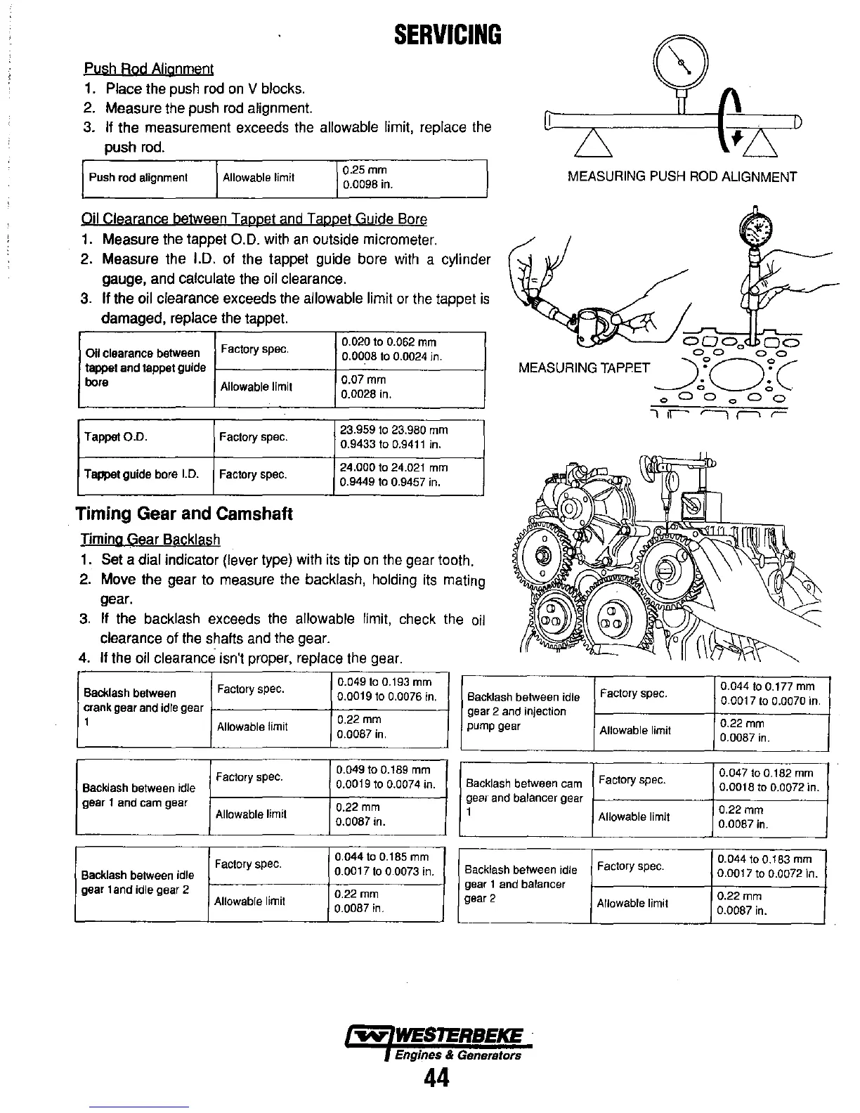
Pysh Rod Alignment
1. Place the push rod
on
V blocks.
2. Measure the push
rod
alignment.
3. If the measurement exceeds the allowable limit, replace the
push rod.
Push
rod
alignment
Allowable
limit
0.25mm
0.0098 in.
MEASURING PUSH ROD ALIGNMENT
Qj! Clearance between Tappet and Tappet Guide Bore
1. Measure the tappet Q.D. with
an
outside micrometer.
2. Measure the I.D. of the tappet guide bore with a cylinder
gauge, and calculate the oil clearance.
3.
If
the oil clearance exceeds the allowable limit
or
the tappet
is
damaged, replace the tappet.
Factory
spec.
0.020 to 0.062 mm
000
0
00
00
00
Oil
clearance
between
0.0008 to 0.0024 in.
tappet
and
tappet guide
bore
Allowable
limit
0.07mm
0.0028 in.
MEASURING TAPPET
~:O~
C
Tappet
0.0.
Factory
spec.
Tappat guide bore
1.0.
Factory
spec.
Timing
Gear
and
Camshaft
Timing Gear Backlash
23.959 to 23.980 mm
0.9433 to 0.94t
tin.
24.000 to 24.02t mm
0.9449 to 0.9457 in.
1. Set a dial indicator (lever type) with its tip
on
the gear tooth.
2. Move the gear to measure the
backlash, holding its mating
gear.
3.
If the backlash exceeds the allowable limit, check the
oil
clearance
of
the shafts and the gear.
4.
If the oil clearance isn't proper, replace the gear.
Factory
spec.
0.049 to
O.
t
93
mm
Backlash
between
O.OOt
9 to 0.0076 in.
Backlash
between
idle
crank
gear
and
idle
gear
t
Allowable
limit
0.22
mm
0.0087 in.
gear
2
and
injection
pump
gear
Factory
spec.
0.049 to
O.
t89
mm
Backlash
between
idle
0.00t9
to 0.0074 in.
Backlash
between
cam
gear
1
and
cam
gear
0.22
rnm
Allowable
limit
0.0087 in.
geal
and
balancer
gear
1
Factory
spec.
0.044 to
O.
t
85
mm
Backlash
between
idle
O.OOt
7 to 0.0073 in.
gear 1
and
idle
gear 2
0.22
mm
Allowable
limit
0.0087 in.
Backlash
between
idle
gear
1
and
balancer
gear 2
~-
Engines & Generators
44
0
00
0
00
.,
,.-
,....,
,--, ,..
Factory
spec.
0.044 to 0.177 mm
O.OOt
7 to 0.0070 in.
Allowable
limit
0.22
mm
0.0087 in.
Factory
spec.
0.047 to
0.t82
mm
O.OOt
8 to 0.0072 in.
Allowable
limit
O.22mm
0.0087 in.
Factory
spec.
0.044 to 0.183 mm
0.0017 to 0.0072 in.
Allowable
limit
0.22mm
0.0087 in.