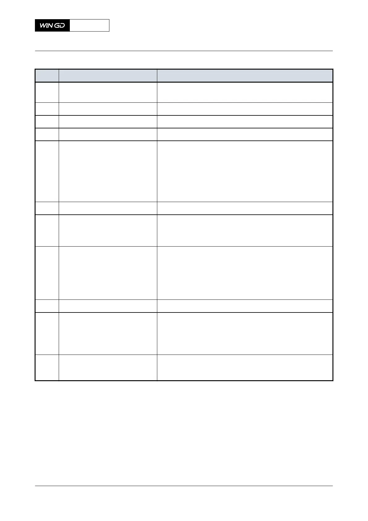
Tab 5-1 iELBA - control cabinet
Item Function Effect
A9 Drive Power Consumption indica-
tion
Shows the electric motor current (in Ampere)
S7 Manual Start button Starts the iELBA (in manual mode)
S8 Manual Stop button Stops the iELBA (in manual mode)
H11 Power 24V indicator light Shows if electric power is on
S5/H5 Error reset button Shows and resets iELBA errors, refer to Table 5-2 - iELBA -
error indication
NOTE: If an error occurs, the indicator light shows the rela-
ted number of flashes.
NOTE: Only reset an error after you have done the related
procedures.
S6 Mode Auto / Manual switch Changes between automatic and manual mode
H3 Swing / Run indicator light Shows the state of the running iELBA:
•
Lamp blinks - iELBA is in swing state
•
Lamp is steady - iELBA is in run state
H4 Synch OK indicator light Shows the synchronisation state of the iELBA:
•
Lamp is steady - iELBA is synchronised to the engine
•
Lamp blinks slowly - iELBA is +/-15° from engine syn-
chronisation
•
Lamp blinks quickly - iELBA is +/-30° from engine syn-
chronisation
S1 Emergency stop button Stops the iELBA immediately
S2/H2 Emerg. Stop Reset button Resets an emergency stop to enable iELBA restart
The integrated indicator light shows as follows:
•
Lamp is on - an emergency stop is active
•
Lamp is off - usual operation
A10 Hour indication Shows the running hours of the electric motor
NOTE: A10 is installed in the control cabinet.
X92DF
AA00-7752-00AAA-043A-A
Operation Manual Integrated electrical balancer (iELBA)
Winterthur Gas & Diesel Ltd.
- 240 - Issue 002 2020-08