13.1.2 Electric connection diagram
The electric connection diagram shows data about the bus routing connections (without cylinder
related signals).
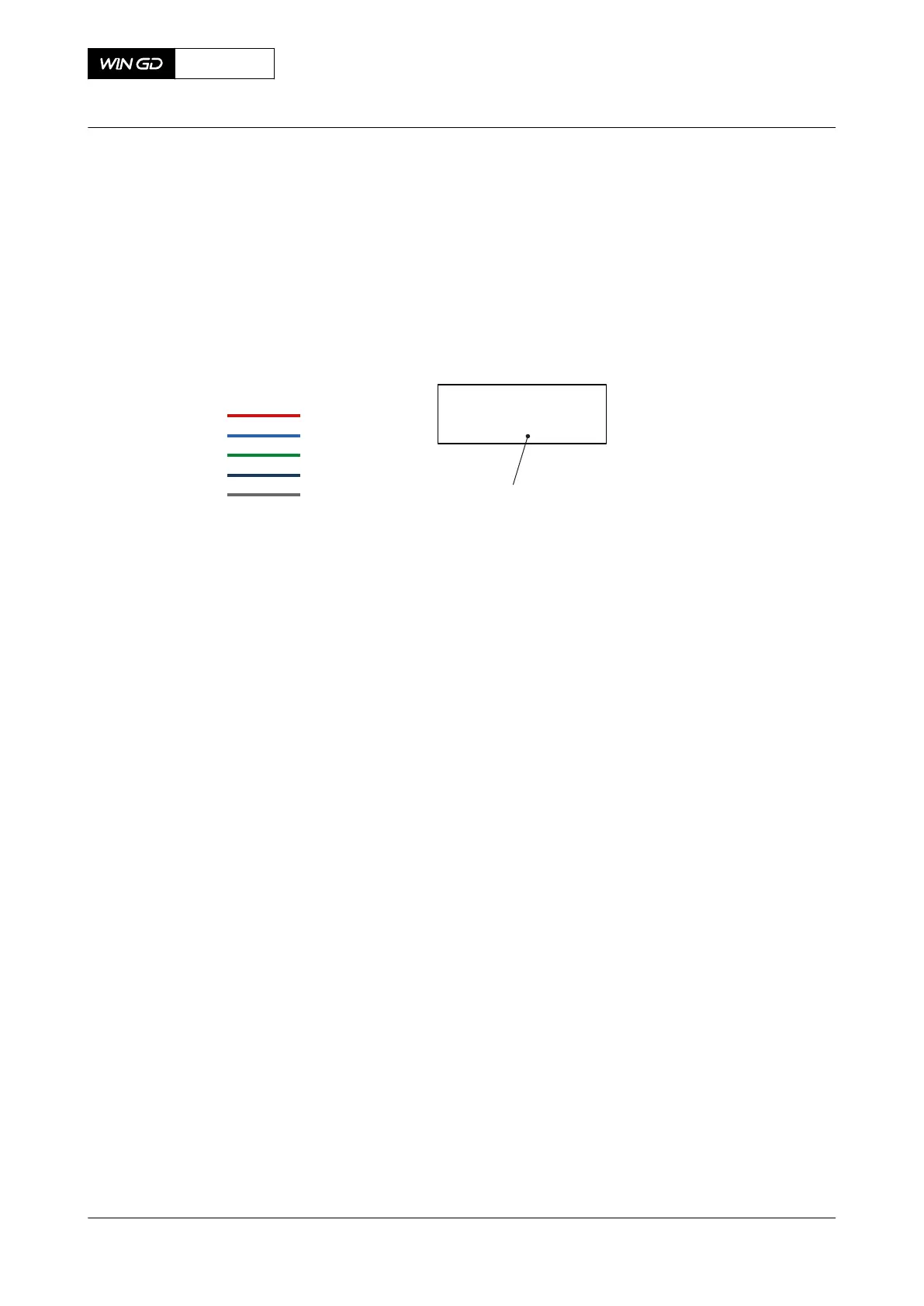
You can find an overview of the used color codes and symbols in Figure 13-4.
Fig 13-4 Color codes and symbols - electric connection diagram
00221
ECR component
Color codes:
Power
Option
Diesel
Speed
Bus
CCM-20 A1
Cylinder #1
13.1.3 Piping and instrumentation diagram
The piping and instrumentation diagrams show data about the piping and instrumentation of the
auxiliary systems of the engine.
X92DF
AA00-0000-00AAA-043I-A
Operation Manual Schematic diagrams - general
Winterthur Gas & Diesel Ltd.
- 608 - Issue 002 2020-08