PROCEDURE
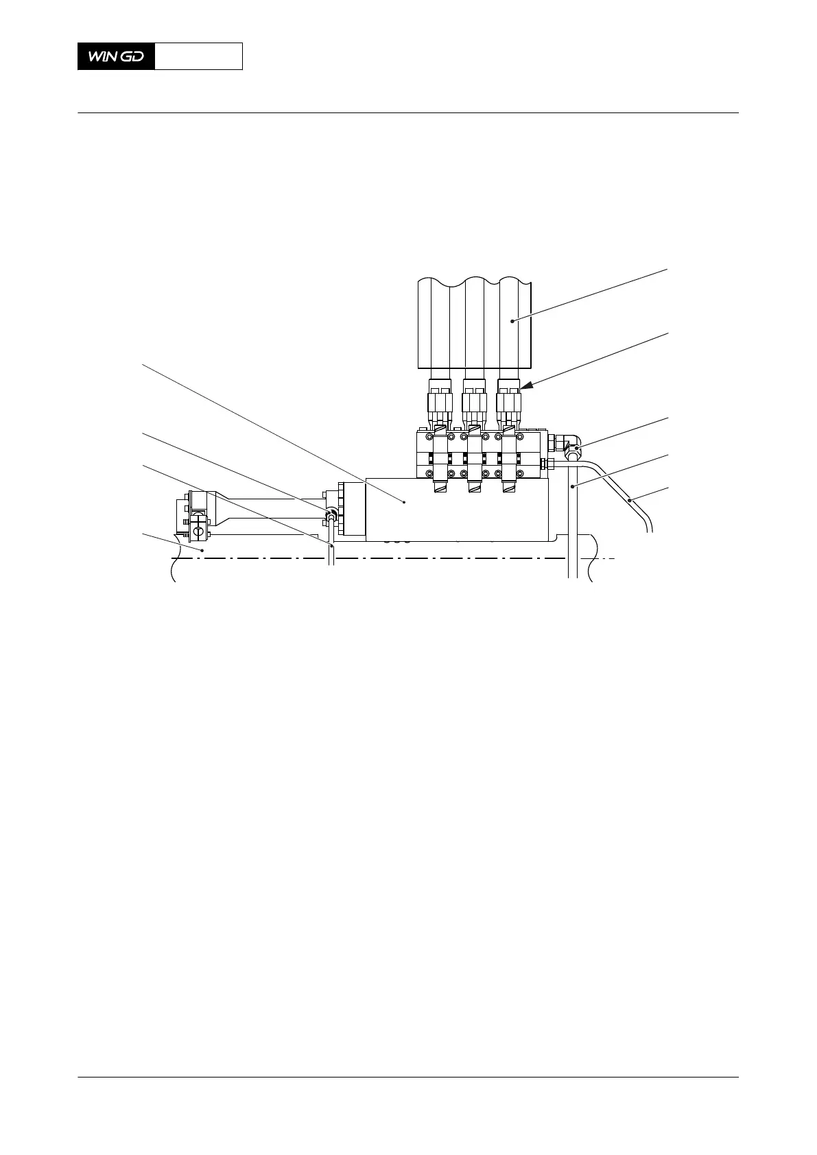
Fig 10-3 Leakage on ICU and pipes (generic)
001
002
003
004
005
006
007
008
009
Legend
001 HP fuel pipe to injection valve 006 Fuel rail
002 Screw 007 Fuel leakage pipe
003 Screw-in union 008 Screw-in union
004 Fuel leakage pipe 009 Injection control unit (ICU)
005 Fuel return pipe
1 Do a check of the level switch LS3446A (if applicable also LS3447A) for free flow. If
necessary, clean the bore of the pipe of the level switch.
2 Carefully do a check of the temperature of the fuel leakage pipe (004, Figure 10-3) of
each injection control unit (ICU) (009) to find the leakage pipe that has a fuel flow.
NOTE: There is a fuel flow in the leakage pipe that has a higher temperature than the
other leakage pipes.
NOTE: As an alternative you can carefully open and close the screw-in union (003) of
each ICU a maximum of two turns to find the leakage pipe that has a fuel flow.
NOTE: Never loosen the screw-in union of the fuel return pipe (005), as this pipe is
under pressure during operation.
3 If there is a leakage pipe (004) that has a fuel flow, do as follows:
3.1 Make sure that the screws (002) are tightened correctly, refer to the
Maintenance Manual 8733-1.
3.2 On the fuel leakage pipe (004), carefully loosen the screw-in union (003) a
maximum of two turns.
3.3 Do a check for fuel flow.
X92DF
AA00-0000-00AAA-311D-A
Operation Manual Examine the ICU or fuel pipes for fuel leakage
Winterthur Gas & Diesel Ltd.
- 543 - Issue 002 2020-08