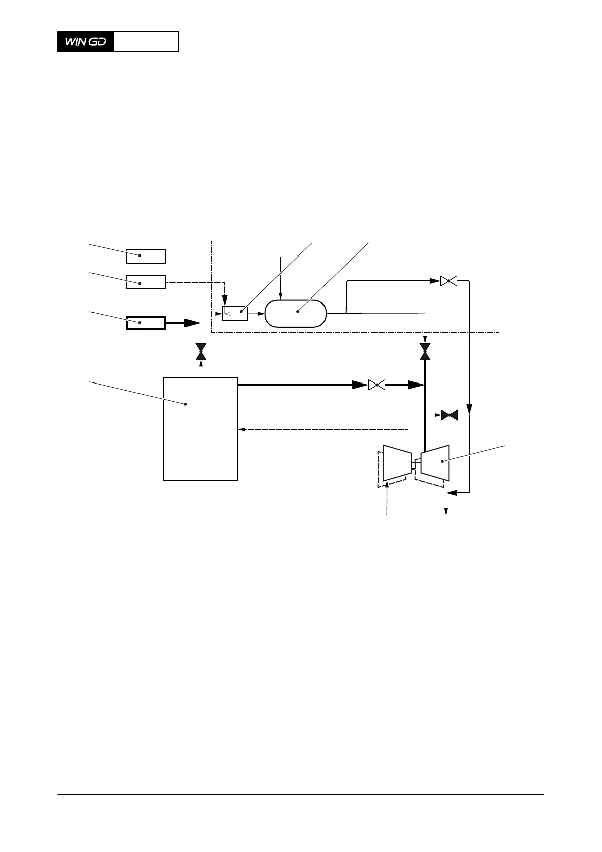
Legend
001 Mixing duct 005 Venting/sealing unit
002 Reactor 006 Urea solution supply unit
003 Turbine of turbocharger 007 Soot blowing unit
004 Engine
Fig 4-29 HP SCR system - purging and venting
V1 V2
V3
V7
V4
003
001
007
006
005
004
002
Legend
001 Mixing duct 005 Venting/sealing unit
002 Reactor 006 Urea solution supply unit
003 Turbine of turbocharger 007 Soot blowing unit
004 Engine
After that procedure, or directly, the venting/sealing unit supplies compressed air to keep a
pressure in the reactor and in the pipes. This makes a seal against the exhaust gas to prevent
damage of the reactor. Make sure that the pressure in the reactor is more than the exhaust gas
pressure.
The valves have the conditions that follow:
•
V1 - Closed
•
V2 - Closed
•
V3 - Open
•
V4 - Controlled by the ECS
•
V7 - Closed, can be opened to decrease the pressure in the reactor
X92DF
AA00-9270-00AAA-043A-A
Operation Manual HP Selective catalytic reduction system
Winterthur Gas & Diesel Ltd.
- 125 - Issue 002 2020-08