2-22
Chapter 2: Installation and Setup
Aug 2012
4 Connect the secondary Accessory/Top Box LCD DVI Cable to the DVI Video Port on
CPU-NXT 3.2, Figure 2-46 (A).
Figure 2-46 Connecting DVI Cable to CPU.
5 Connect the Main LCD DVI Cable.
6 Connect the SPDIF Cable, Figure 2-30 (A), as defined in Table 2-2.
7 Connect the USB Cable, Figure 2-30 (D), as defined in Table 2-2.
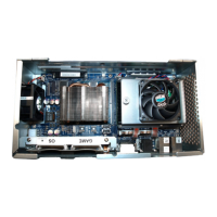
8 Connect the DC Power Cable P3 connector to the 12-pin Mini-Fit Jr. Power Input located on
the side of CPU-NXT 3.2, Figure 2-47 (A).
Figure 2-47 Connecting DC Power Cable to Mini-Fit Jr. Power Input.
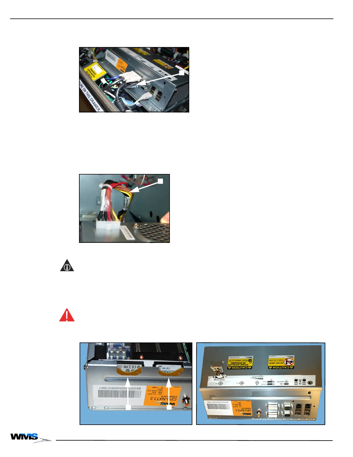
9 Install the two CompactFlash® cards by gently pushing down on the center of the card,
Figure 2-48:
NOTE: The front of the Compact Flash cards face the video card heatsink, and the back of the
CompactFlash cards face the CPU faceplate.
Install the operating system (OS) card into the left CompactFlash® slot above the OS label
located on the SSD bracket, Figure 2-48 (A)
Install the game software card into the right CompactFlash® slot above the GAME label
located on the SSD bracket, Figure 2-48 (B).
WARNING: Do not force the CompactFlash® card into the slot. If the card does not engage easily, it
is likely installed backwards.
Figure 2-48 Installing CompactFlash® cards w/Logic Door open (left) and w/Logic Door closed (right).
 Loading...