Planning
24 | WOLF GmbH 3066501_201910
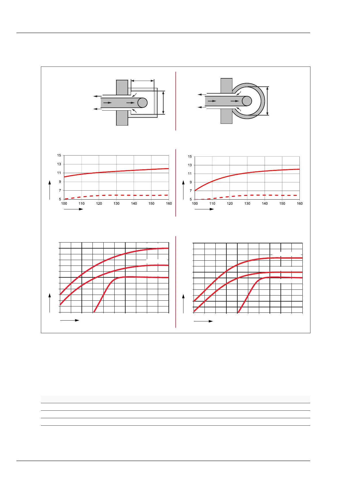
4.6.5 Minimum shaft sizes
Room sealed operation C93x
Assuming: 1 x 87° bend + 1.5 m horizontal with 87° support bend
a
a
Ø
10
8
110 120 130 140 150 160
12
14
16
18
20
22
24
26
28
30
32
COB-2-15/-20
[m]
a x a [mm]
10
8
12
14
16
18
20
22
24
26
28
30
32
120 130 140 150 160 170
Ø [mm]
[m]
DN80 (COB-2-15/20/29), DN110 (COB-2-40)
Ø [mm]
[m]
[m]
a x a [mm]
DN60 (COB-2-15)
COB-2-29
COB-2-40
COB-2-15/-20
COB-2-29
COB-2-40
Fig. 4.5 Shaft size
q Max. vertical length [m]
w Rigid ue
e Flexible ue
OpenueoperationB23,B33androomsealedoperationC53(x)
Due to the need for permanent secondary ventilation between the ue and shaft in accordance with DIN
18160, when installing rigid and exible air/ue gas lines in a shaft, the following min. shaft sizes are
required:
Circular diameter Rectangular width
DN 60 130 mm 110 mm
DN 80 150 mm 130 mm
DN 110 190 mm 170 mm
Table 4.11 Minimum shaft size