Appendix
3066501_201910 WOLF GmbH | 85
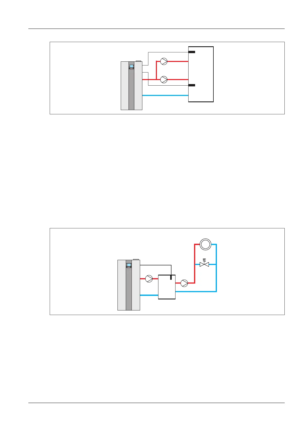
BSP cylinder with header sensor
Fig. 12.8 Systemconguration11-BSPcylinderwithheadersensor
q Input: Cylinder temperature sensor
w Input E2: Header temperature sensor
e Cylinder primary pump
r Feed/heating circuit pump
t Cylinder temperature sensor
y Header temperature sensor
– Burner starts subject to demand from the header temperature control (heating mode) or in case of
cylinder demand.
– Feed/heating circuit pump enabled as a feed pump (heating mode only). Not activated during cylinder
heating.
– Header temperature control (heating mode only)
– Input E2: Header sensor (heating mode only)
– In case of cylinder heating, the reference temperature is provided by the boiler sensor.
– Heating circuit with MM-2! see hydraulic schemes no. 16-52-018-003, 16-52-018-005 and
16-52-018-006
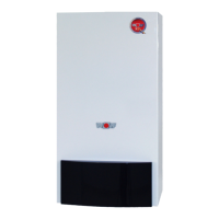
12.3.4 Systemconguration12
Low loss header with header sensor + direct heating circuit (A1)
Fig. 12.9 Systemconguration12-Lowlossheaderwithheadersensor
q Input E2: Header temperature sensor
w Feed/heating circuit pump
e Header temperature sensor
r A1 = heating circuit pump
t Direct heating circuit
– Burner starts subject to demand from the header temperature control
– Feed/heating circuit pump enabled as a feed pump for header demand
– Header temperature control
– Input E2: Header sensor
– Parameter 08 (T-Flowmax): 90°C
– Parameter 22 (max. boiler temp.): 90°C
– Parameter 14 (output A1): HCP