Appendix
3066501_201910 WOLF GmbH | 83
12.3.1 Systemconguration01
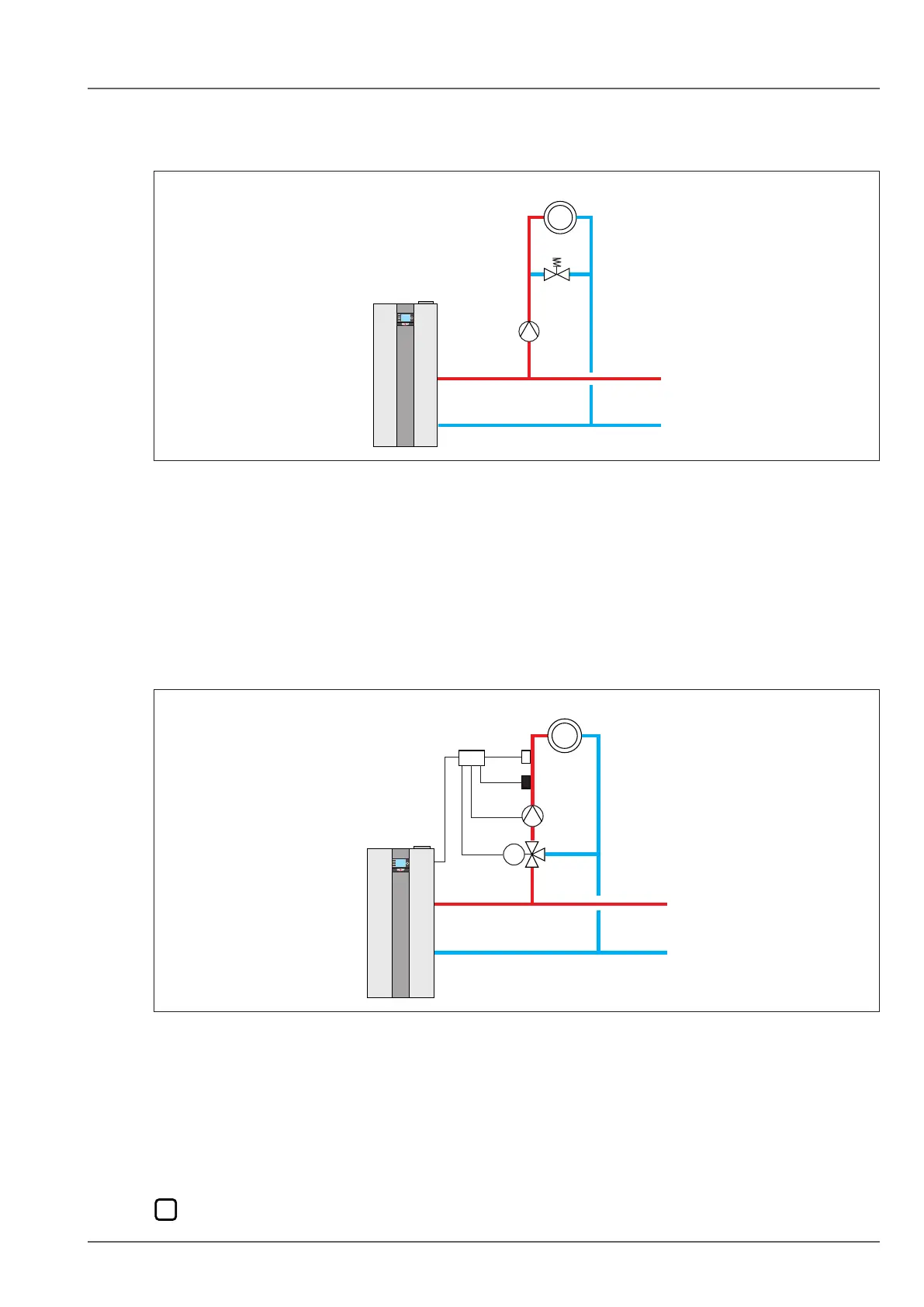
Direct heating circuit on the wall mounted condensing boiler + further optional mixing circuits via
mixer modules (factory setting)
Fig. 12.4 Systemconguration01-Directheatingcircuitonthewallmountedcondensingboiler+further
optional mixing circuits
q Feed/heating circuit pump w Direct heating circuit
– Burner starts subject to demand from the direct heating circuit or optionally connected mixing circuits.
– Feed/heating circuit pump enabled as a heating circuit pump
– Boiler temperature controller; set value is specied by heating circuit or mixing circuits
– Input E2: not assigned
12.3.2 Systemconguration02
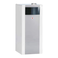
One or more mixing circuits via mixer modules (no direct heating circuit on the condensing boiler)
Fig. 12.5 Systemconguration02-Oneormoremixingcircuits
q MM-2 mixer module w Mixing circuit1
Burner is enabled subject to demand from the connected mixing circuits.
– Boiler temperature controller; set value is specied by mixing circuits
– Input E2: not assigned
– Feed/heating circuit pump not enabled as a heating circuit pump
12.3.3 Systemconguration11
There are three possible hydraulic schemes for system conguration 11.


 To Next Page