Planning
28 | WOLF GmbH 3066501_201910
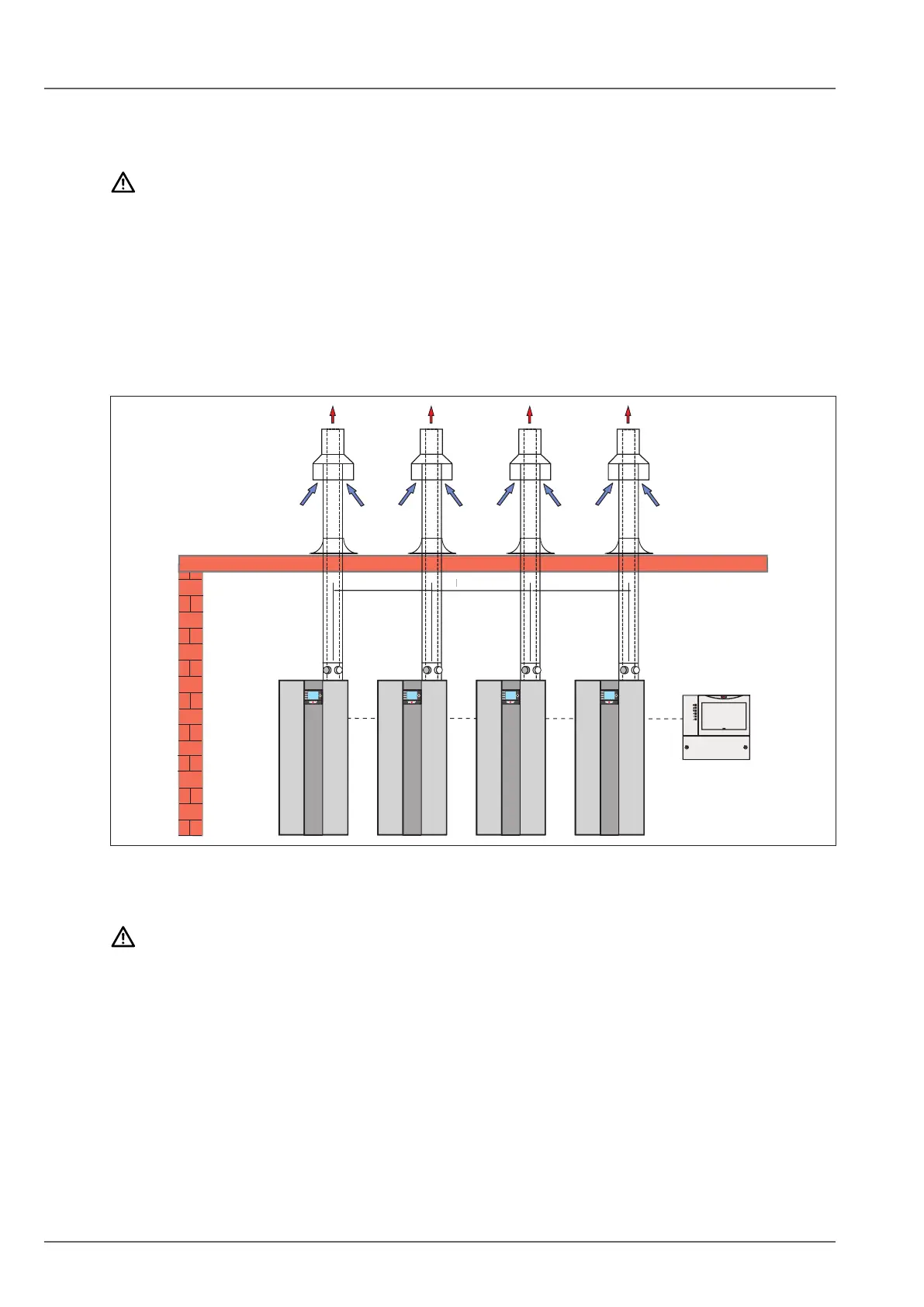
4.7.5 Air/uegasrouting
Separateconcentricbalancedue
NOTE
Fluegascanbedrawnbackinthroughadjacentueoutlets.
Heat generator faults
► Maintain a clearance of 600 mm.
► All outlets must be at roughly the same height
Do not exceed the maximum permissible route length.
The calculated length comprises the straight pipe length and the length of the pipe bends. In this
calculation, an 87° bend is calculated as being 2.0 m and a 45° bend as being 1.2 m.
Maximum permissible route length:
– DN 80/125 max. 18 m
– DN 110/160 max. 14 m
Fig. 4.9 Cascadecontrolwithseparate,vertical,concentricbalancedue,typeC33x.
Fluegasroutingwithheader(uegascascade)
DANGER
Escapeofuegases!
Risk of asphyxiation or severe to life-threatening poisoning.
► A ue cascade is only permitted with a tested ue gas damper.
Design according to EN 13984-1. Comply with all building regulations and requirements in your country.
Heat generators with common ue routing are only suitable for open ue operation (type B23). There
must be an aperture in the installation room that opens to the outside and has a clear cross-section of at
least 150 cm².
In addition to the bends connected to the heat generator, a maximum of two 87° diverters may be
installed.
Min. 600 Min. 600 Min. 600