Installation
3066501_201910 WOLF GmbH | 35
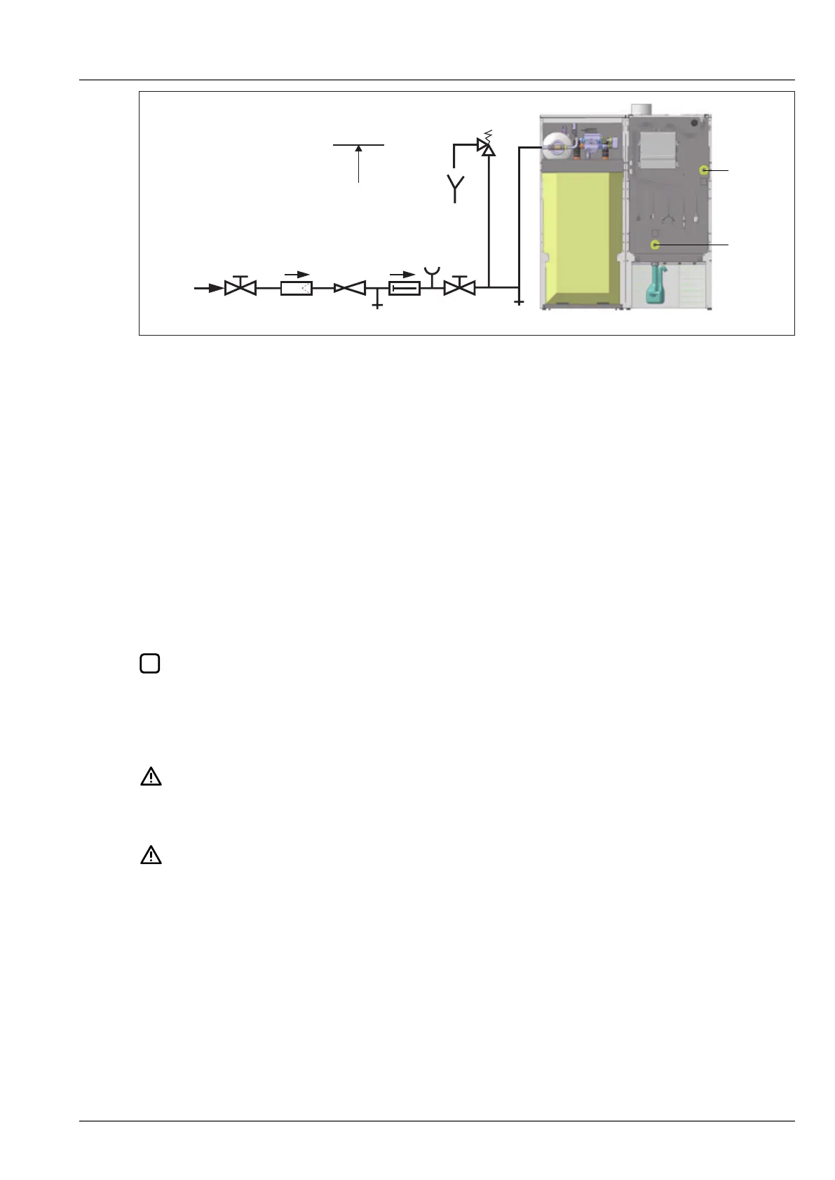
Fig. 5.10 Cold water connection to DIN 1988
q Cold water supply
w Shut-off valve
e Drinking water lter
r Pressure reducing valve
t Drain
y Non-return valve (individually tested)
u Pressure gauge connection
i Shut-off valve
o Above top edge of the cylinder
a Safety valve (individually tested)
s Heating ow
d Heating return
5.7 Connecting the oil line
► Connect the system.
► A lter/air vent valve combination with an integrated shut-off valve from the WOLF product range must
be installed.
► Check the oil line in accordance with TRÖl for the following:
– fault-free condition
– properly installed
– no leaks
This inspection is performed in the following cases:
– Before commissioning
– For underground oil lines, before they are covered
– After work on the oil lines (except for oil lter changes)
5.7.1 Connectingthelter/airventcombination
CAUTION
Oil leak!
Drinking water may be contaminated by hazardous substances.
► Install the oil line with the system disconnected from the power supply.
NOTE
Contaminants in the oil line
System damage
► Flush the oil line before commissioning!
► Route the oil line through the back panel.
✔ Oil line projects no more than 90 cm from the casing.
► Secure the lter/vent combination (integrated shut-off valve) and retainer to the positions provided for
this.
5.7.2 Connecting the anti-lift valve
► Connect anti-lift valve to output A1
► Set A1 (ext. fuel valve) parameter (7.2.7 HG14: Function output A1).
If output A1 is already being used (e.g. for a DHW circulation pump),