Installation
38 | WOLF GmbH 3066501_201910
5.9 Connectingthebalancedue
► Comply with the planning guidance 4.6 Air/ue gas routing.
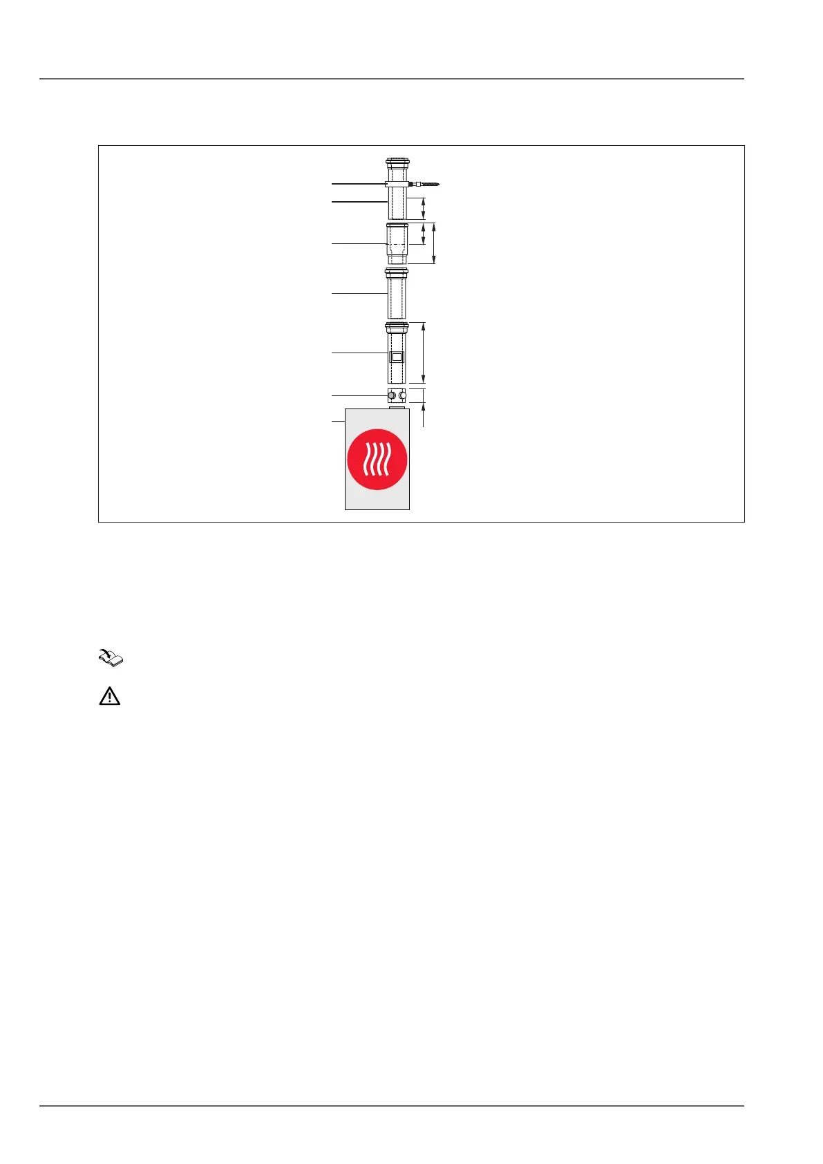
250
5050
DN60/100: 235
DN80/125: 200
90
Fig. 5.14 Example:balancedue[mm]
q Heat generator
w Appliance connection with ue gas test port
e Inspection piece
r Balanced pipe ue
t Disconnect device
y Spacer clip
5.9.1 Installingthebalancedue
Installation information for balanced ue system
NOTE
Inadequateinclineforbalancedue!
Corrosion of components or faults.
► Install the balanced ue with an angle of at least 3° (6 cm/m) relative to the heat generator.
► Follow the installation instructions for the balanced ue system.
► Never install damaged parts.
► Create ue connections using sockets and gaskets.
► Ensure that gaskets are tted correctly.
► Always arrange sockets against the direction of the condensate ow.
► Always trim the ue on the smooth side, never on the coupling side.
► Bevel or deburr trimmed ues to ensure gas-tight installation of pipe joints.
► Remove contamination before installation.
► Wet or lubricate all air/ue gas joints prior to installation, e.g. using soap suds or a suitable grease
without silicone.
► Lines must be secured with brackets.
Connectingtheapplianceconnectionwithuegastestport
► Install appliance connection with ue gas test port (2) (Fig. 5.14 Example: balanced ue [mm]) at the
connection point of the heat generator (1).
Fit inspection piece
If an inspection aperture is required for the balanced ue,
► insert a balanced ue pipe with inspection aperture.