Installation
32 | WOLF GmbH 3066501_201910
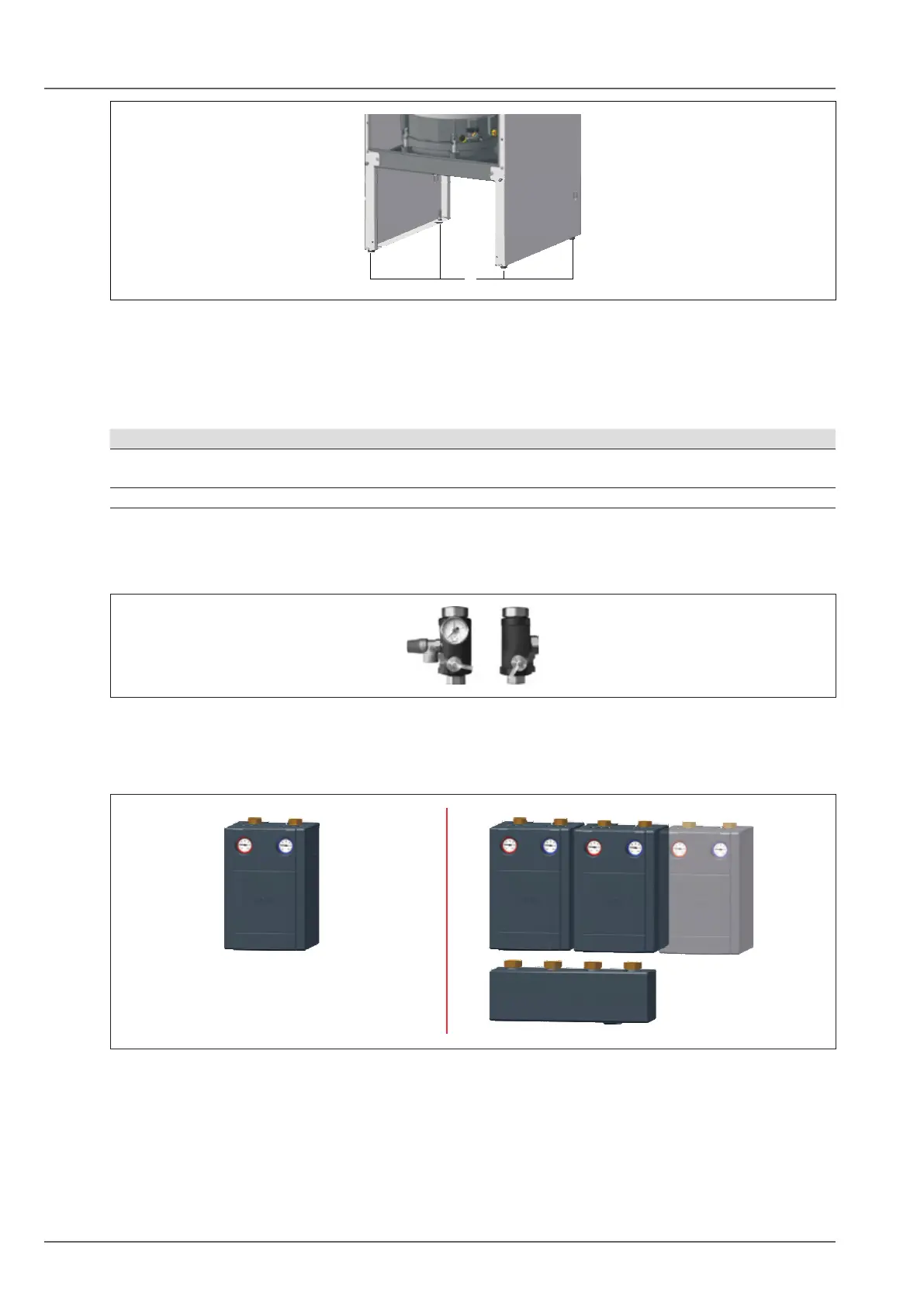
Fig. 5.4 Level the heat generator
q Adjustable feet
5.5 Installing the safety assembly and pipe assembly
► Install the safety assembly and necessary pipe assemblies.
Number of pipe assemblies Possible installation position
1-2 – Side casing
– Wall (left, right, rear)
>3 – Wall (left, right, rear)
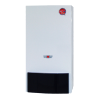
Safety assembly
► Install the safety assembly for the heating ow and return.
► Route the discharge pipes of the safety valves into a drain outlet.
Fig. 5.5 Safety assembly with levelling part
Pipe assembly
► Install the pipe assembly on the safety assembly.
Fig. 5.6 Pipe assemblies
q Pipe assembly for 1 heating circuit w Pipe assembly for 2 or 3 heating circuits with
manifolds