Planning
3066501_201910 WOLF GmbH | 27
4.7.3 Heating system
Heating circuit
The following types of connections shall be selected to ensure the heating water ow rate through every
heat generator is as even as possible:
– For precise hydronic balancing, t a line regulating valve in the supply line to every heat generator.
– Design the ow and return lines with the same length for the ow and return according to the
Tichelmann system to ensure the pressure drop in every line is equally high.
Low loss header
It must not be possible for the on-site heating circuit pumps or primary pumps to inuence the function of
the heat generator. A low loss header should therefore be installed upstream of the heating water circuit
or DHW cylinder circuit.
Ensure that the heating water ow rate through the heat generator is set lower than that through the
subsequent heating circuit. The ow rate should be set upstream of the low loss header via a line
regulating valve or buttery valve.
Hydraulic separation
Instead of the low loss header, a heat exchanger can be installed. If pipes are used which are not
impermeable to oxygen, this is a requirement in any case.
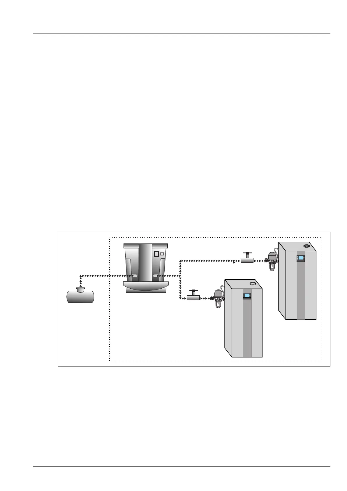
4.7.4 Fuel supply
The oil lines must be sized in accordance with TRÖl.
Each heat generator must be provided with its own oil supply.
If there is only one oil storage installation, this supply must be arranged centrally via a suction unit.
The suction unit must be installed as close to the boiler cascade as possible.
Fig. 4.8 Fuel supply
q Oil storage installation w Suction unit