Appendix
82 | WOLF GmbH 3066501_201910
gn/ge
M
230V~
br
bl
A1
N
L1
L1
LP
N
SF
1
2
AF
E1
eBUS
+
-
1
2
a
b
E2
a
b
1 2
1 2
1 2
1 2
1 2
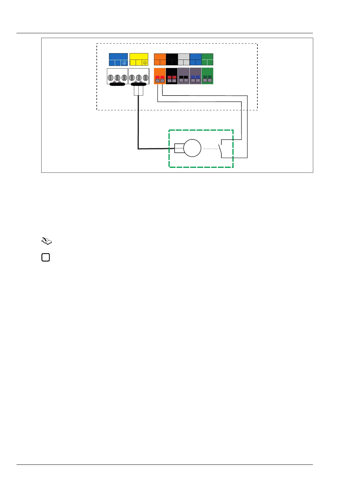
Fig. 12.3 HCM-2 electrical connection
q A1 (programmable output)
w E1 (programmable input, e.g. “Flue gas damper”)
e Extract air damper motor
r Limit switch
When the limit switch is open, the burner is blocked both for DHW and heating, as well as for emissions
tests and frost protection.
12.3 HG40:Systemconguration
Hydraulic and electrical details: "Hydraulic System Solutions" technical guide.
Shut-off valves, air vent valves and safety equipment are not depicted in these hydraulic diagrams.
► These should be provided for each system individually, in line with the applicable standards and
regulations.