Installation
40 | WOLF GmbH 3066501_201910
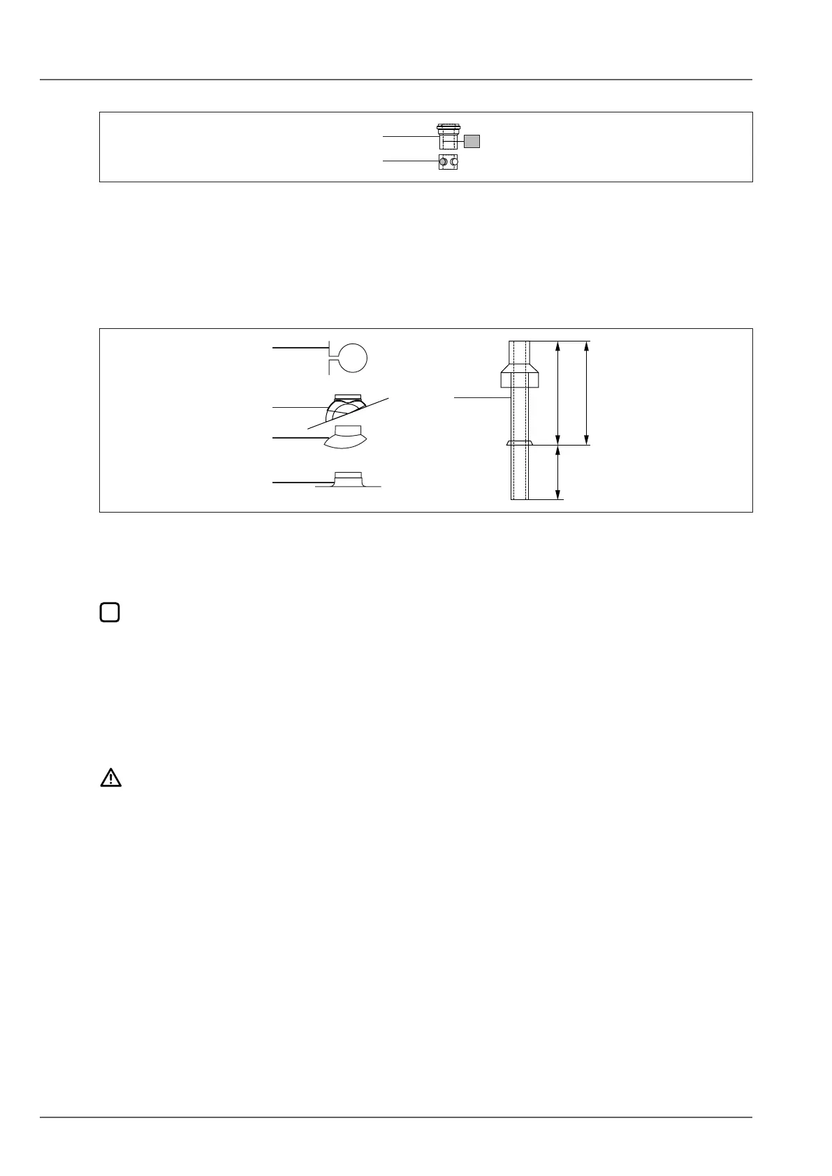
5.9.2 Installingtheuegasdamper(cascadeoperationonly)
Fig. 5.16 Flue gas damper
q Appliance connection with ue gas test port w Flue gas damper
► Insert the ue gas damper (2) fully into the appliance collection with ue gas test port (1).
► Connect the ue gas damper to the power supply (5.10.6 Connect the ue gas damper to the power
supply (cascade operation only).).
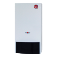
5.9.3 Installing the roof outlet
650550-1050
1250
Ø 130
Fig. 5.17 Roof outlet [mm]
q Flat roof collar
w Adaptor for “Klöber base panels”
e Universal tile
r Mounting bracket
t Roof outlet
The roof outlet (5) may only be installed in its original condition. Modications are not permissible.
Universal tile (3) can be combined with adaptor for “Klöber base panels” (2).
► Afx at roof collar (1) into roof cover.
► When using universal tile (3), observe the installation instructions on the cowl regarding roof pitch.
► Guide the roof outlet (5) through the roof from above.
► Secure vertically with mounting bracket (4) to a rafter or brickwork.
5.10 Electrical connection
DANGER
Risk of electrical voltage even when the ON/OFF switch is set to OFF!
Danger of death from electrocution
► Isolate the entire system from the power supply across all poles (e.g. by removing the mains fuse
or by means of a main switch or heating emergency stop switch).
► Check that the appliance is isolated from the power supply.
► Safeguard the system against reconnection.
5.10.1 Power supply
Power cable: exible, 3 x 1.0 mm² or rigid, up to 3 x 1.5 mm²
The maximum current carrying capacity of the outputs is 1.5 A. Do not exceed a total of 4 A.
► In case of a permanent connection, connect the power supply via a mains isolator (e.g. fuse, heating
system emergency stop switch) that ensures at least 3 mm contact separation.