Installation
3066501_201910 WOLF GmbH | 39
Fit disconnect device
► Slide the disconnect device (6) (Fig. 5.14 Example: balanced ue [mm]) fully into the socket (5).
► Slide the next balanced ue pipe (5) 50 mm into the socket of the disconnect device (6).
► Ensure that the balanced ue pipe (5) is fully secured in this position, e. g. with a pipe clamp (7) or with
a locking screw on the air side.
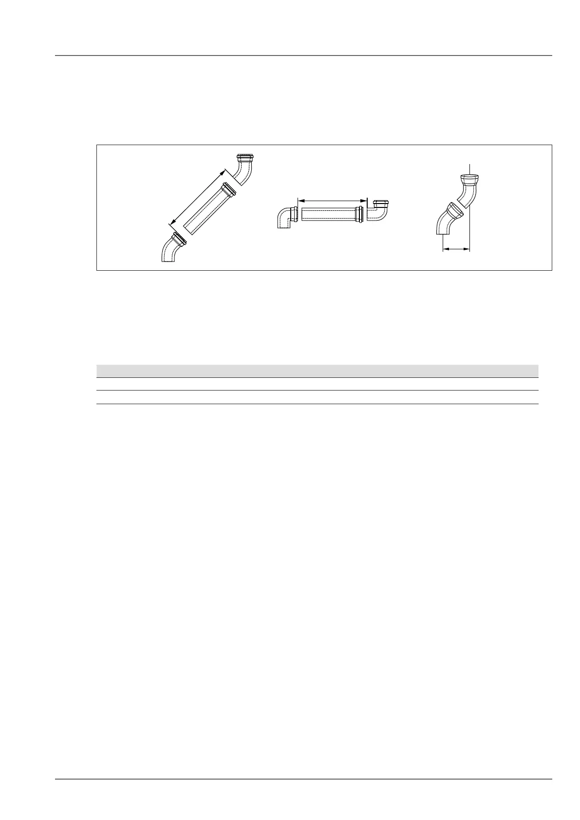
Calculating clearance and offset
A
B
A
Fig. 5.15 Balanceduepipelength
A Clearance
B Offset
q Balanced ue pipe length
w 45° bend
e Bend 87°
► Determine distance (A).
► Balanced ue pipe (1) length always approximately 100 mm longer than clearance (A).
► Take the offset (B) into account.
Bend B
87° At least 204 mm
45° At least 93 mm
Table 5.1 Offset bend
Installingabalancedueinanexistingchimney/duct
► Make sure that there is appropriate clearance between the outside of the ue and the wall of the duct
(Fig. 4.6 Minimum shaft size [mm]).
► Flue lines, retaining straps and spacers must be installed in channels and ducts in such a way that the
ventilated cross-section can be inspected and cleaned.
► Close cleaning apertures in ducts with chimney cleaning covers which have been assigned an
approved test mark.
► The outlets of ue lines in ducts must be designed so that the following requirements are met:
– no ingress of precipitation
– secondary ventilation can ow freely
► It must be possible to remove removable covers without tools and they must be secured to prevent
them falling.