Manual 37278B GCP-30 Series - Genset Control
© Woodward Page 31/174
Controller
≡≡≡≡≡≡≡≡≡≡≡≡≡≡≡≡≡≡≡≡≡≡≡≡≡
WARNING
Incorrect settings may lead to the errors in measurements and failures within the control unit resulting
in destruction of equipment or injury to personnel.
Parameter 45
Configure
controller YES
Configuration of the controller YES/NO
Parameters are grouped together in blocks to permit quicker navigation through the
large number of configuration screens. Selecting "YES" or "NO" has no effect if
controlling or monitoring is performed. This parameter has the following effects:
YES .............. The configuration screens in the next block are displayed and can ei-
ther be viewed ("Select" push-button) or modified ("Cursor→", "Di-
git↑" or "Select" push-buttons).
NO ................ The parameters in the next block are not displayed, cannot be mod-
ified and are therefore skipped.
Table Of Set Point Values
Automatic 1 Automatic 2 Control via
interface
External
set point value
Specification
of the set point value through
energized insignificant insignificant insignificant Set point 1 (Parameter 46)
de-energized energized OFF OFF Set point 2 (Parameter 47)
de-energized energized insignificant ON Externally via 0/4-20 mA input
(Package XP, Option T701; Para-
m
eter 91)
de-energized energized ON OFF Externally via interface
de-energized de-energized OFF OFF Standby only: Emergency power
(AMF)
Table 3-3: Set point value table
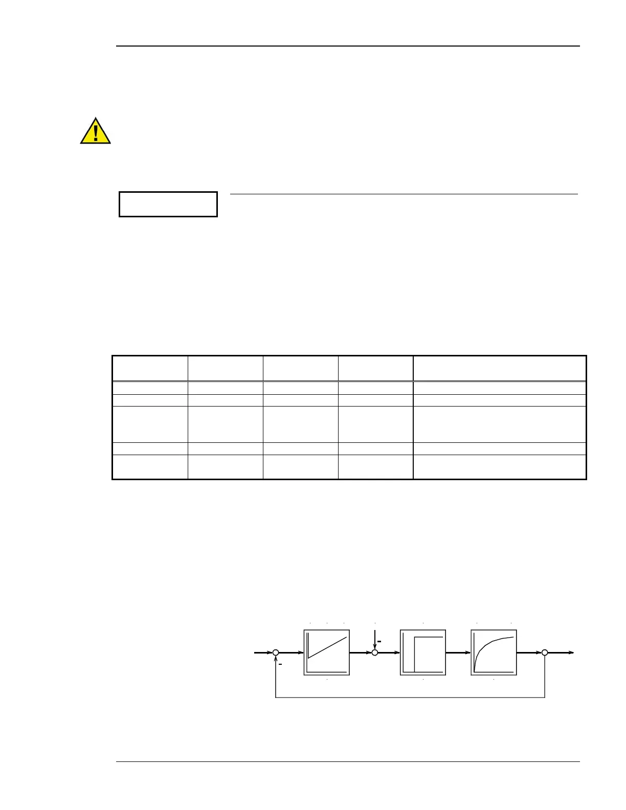
Analog Controller Outputs (Package Q, Option Q)
As an alternative to a three-position controller output, the control may also be equipped with an analog controller
output. If this option is selected, additional screens are displayed in the configuration mode. The analog PID con-
troller forms a closed-loop control loop with the controlled system (usually a first-order lag element). The para-
meters of the PID controller (proportional-action coefficient K
PR
, derivative-action time T
V
, and reset time T
n
)
can be modified individually. The additional configuration screens are used for this purpose.
Kp T1
Controlled system (PT1)PID controller
Kpr Tn Tv
Lag element (Tt)
Influenciny
quantity
Tt
Figure 3-1: Control loop

 Loading...


