Manual 37278B GCP-30 Series - Genset Control
© Woodward Page 51/174
Prerequisites: The rated system frequencies, the start/stop parameters, and the breaker logics must all be set to
the same values for all controls participating in the distribution control.
Description of the interface for distribution control: Distribution control is based on a multi-master-capable
bus between the controls. This structure enables the parallel operation of up to 14 gensets.
The following must be noted to ensure proper operation:
• The maximum bus length must not exceed 250 meters (820 feet).
• The bus must be terminated at each end with terminating resistors that correspond to the wave impedance of
the bus cable (approx. 80-120 Ω).
• The bus must be of a linear structure. Dead-end feeders are not permissible.
• Shielded "Twister-Pairs" are recommended for use as the bus cable (e.g.: Lappkabel Unitronic LIYCY (TP)
2×2×0.25, UNITRONIC-Bus LD 2×2×0.22).
• The bus cable must not be routed in the vicinity of heavy current power lines.
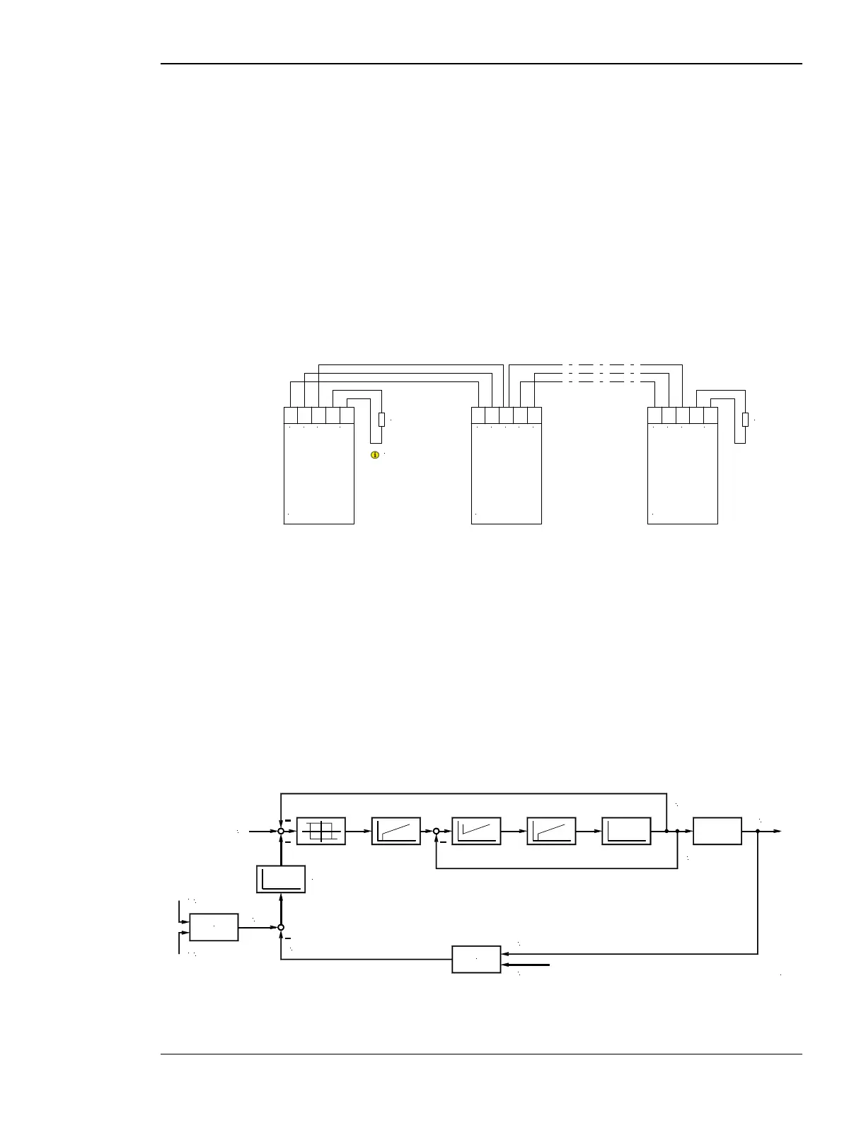
Wiring diagram
GND
CAN-L
CAN-H
GND
GND
CAN-L
CAN-H
CAN-L
CAN-H
CAN-L
CAN-H
CAN bus
Termination
Termination
resistor
Note:
The termination has to be
performed with a resisitance,
which corresponds to the
impedance of the used cable
(e.g 120 Ohms)
CAN bus CAN bus
Termination
Termination
resistor
Figure 3-4: CAN bus load/var sharing, wiring diagram
Diagram of load/var sharing via the CAN bus: The parameter "Active load sharing factor" determines if and
how a generator carries out real power or frequency control when paralleled with other generators in an isolated
operation. This parameter is defined as a percentage. In figure below 10 % means increased real power control
and 99 % increased frequency control. This parameter must be configured individually for each generator.
In the illustrated control system, it must be noted that each control calculates the mean utilization factor of all
controls from the data transmitted via the CAN bus and then compares this with its own utilization factor. The
utilization factor is compared with the reference variable and results in a new reference variable. Frequency and
real power control are carried out simultaneously in these controls (corresponding to the reference variable).
Frequency control is carried out via the measured voltage/frequency of the voltage system. The Pickup is used
merely for monitoring functions, or is available as a current control value to the secondary controller.
P
f
actual [kW]
nominal [kW]
actual [Hz]
Utilization factor of this engine [%]
P
P
P
Σ
Calculation
actual (via CAN)
diff [%]
f
P
Σ
set
nominal (via CAN)
Leading value 10..99 [%]
10 % = only P control
99 % = only f control
P
P
Calculation
2001-08-06 Leistungsverteilung Blockschaltbild.skf
actual [kW]
n
actual [min-1]
Figure 3-5: CAN bus load/var sharing, diagram

 Loading...


