Manual 37278B GCP-30 Series - Genset Control
© Woodward Page 41/174
Parameter 73
Volt.controller
gain Kp 00.0
V controller: gain 0.1 to 99.9
The gain factor K
p
influences the operating time of the relays. By increasing the
gain, the response is increased to permit larger corrections to the variable to be con-
trolled. The farther out of tolerance the process is the larger the response action is
to return the process to the tolerance band. If the gain is configured too high, the
result is excessive overshoot/undershoot of the desired value.
Analog controller (Package Q, Option Q: setting 'ANALOG')
Parameter 74
V/Q contr.output
----------------
Package Q, Option Q only
V controller: range see below
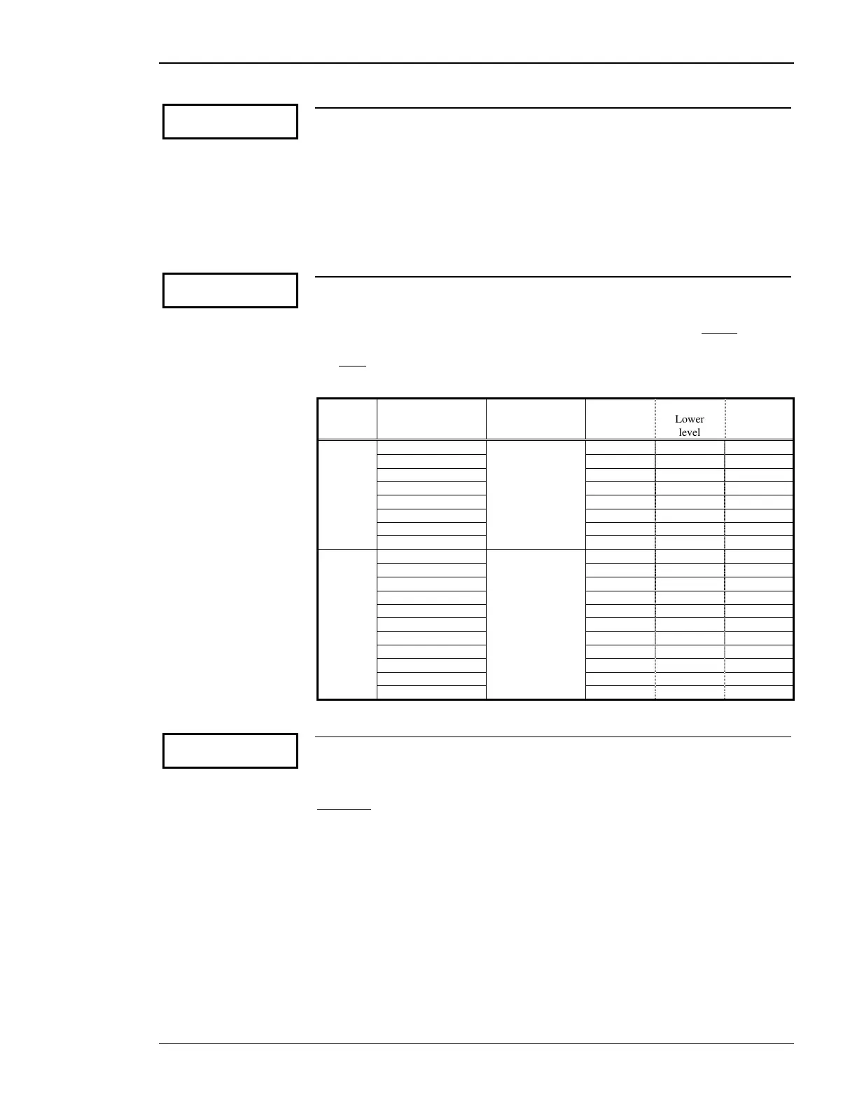
If the Parameter 70 has been configured to "ANALOG" this parameter must be
configured to the appropriate type of analog controller. The range of the analog
output is configured here. If a current analog output is to be utilized do not
install a
jumper between terminals 11/12. If a voltage analog output is to be utilized, a jum-
per must
be installed between terminals 11/12. The following analog output ranges
may be used with this controller.
Type Setting in above
configuration
screen
Jumper
between
term. 11/12
Range
Lower
level
Upper
level
Current +/-20mA (+/-10V) no +/-20mA -20 mA +20 mA
+/-10mA (+/-5V) +/-10mA -10 mA +20 mA
0 to 10mA (0 to 5V) 0-10mA 0 mA 10 mA
0 to 20mA (0 to 10V) 0-20mA 0 mA 20 mA
4 to 20mA 4-20mA 4 mA 20 mA
10 to 0mA (5 to 0V) 10-0mA 10 mA 0 mA
20 to 0mA (10 to 0V) 20-0mA 20 mA 0 mA
20 to 4mA 20-4mA 20 mA 4 mA
Voltage +/-20mA (+/-10V) yes +/-10V -10 Vdc +10 Vdc
+/-10mA (+/-5V) +/-5V -5 Vdc +5 Vdc
+/-3V +/-3V -3 Vdc +3 Vdc
+/-2.5V +/-2.5V -2.5Vdc +2.5 Vdc
+/-1V +/-1V -1 Vdc +1 Vdc
0 to 10mA (0 to 5V) 0 to 5V 0 Vdc 5 Vdc
0.5V to 4.5V 0.5 to 4.5V 0.5 Vdc 4.5 Vdc
0 to 20mA (0 to 10V) 0 to 10V 0 Vdc 10 Vdc
10 to 0mA (5 to 0V) 5 to 0V 5 Vdc 0 Vdc
4.5V to 0.5V 4.5 to 0.5V 4.5 Vdc 0.5 Vdc
20 to 0mA (10 to 0V) 10 to 0V 10 Vdc 0 Vdc
Parameter 75
Stepper sign.vol
(min.) 000%
Package Q, Option Q only
V controller: minimum value 0 to 100%
This parameter permits the operator to clamp or limit the lower analog output val-
ue.
Example:
A 1 to 4V analog output is needed for the voltage controller to operate
properly. A jumper is installed on the terminals as described above and the analog
output of 0 to 5V is selected. The number to be configured in this parameter is de-
termined by dividing the desired lower limit by the range (1/5=0.20 or 20%). 20%
is the value to be configured in this parameter.

 Loading...


