Manual 37365A GCP-30 Series Packages - Genset Control
© Woodward Page 51/179
Parameter 79
Analog input
0-00mA
XPD, XPQ
Power set point value: range 0 to 20 / 4 to 20 mA
The analog input measurement range is selected in this parameter. The user may se-
lect from 0 to 20 mA or 4 to 20 mA to match the source of the input.
0 to 20 mA ... Minimum set point value corresponds to 0 mA;
maximum set point value corresponds to 20 mA.
4 to 20 mA ... Minimum set point value corresponds to 4 mA;
maximum set point value corresponds to 20 mA.
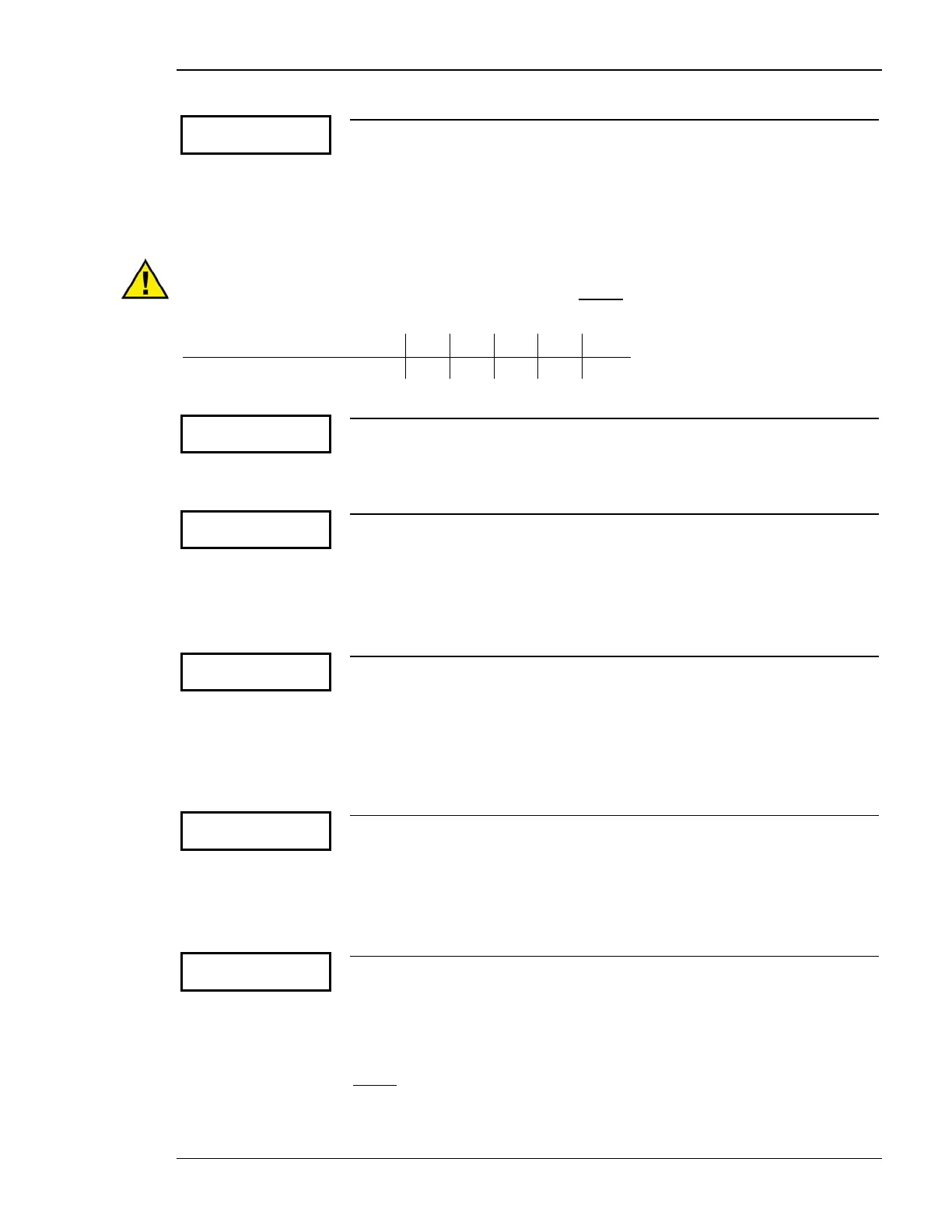
CAUTION
It is possible to scale the real power interchange set point. Do not configure a base load operation (C)
with an import (I) or export (E) operation. The chart below shows permissible combinations of the ana-
log input current levels and import, export, and base load power operations.
External set point 0/4 mA C I E I E
External set point 20 mA C I E E I
Parameter 80
Ext.setpoint
0mA 0000kW
XPD, XPQ
Power set point value: scaling-minimum value C/I/E 0 to 9,999 kW
The minimum value of the generator real power that corresponds to 0/4 mA is de-
fined here (e. g. 0 kW).
Parameter 81
Ext.setpoint
20mA 0000kW
XPD, XPQ
Power set point value: scaling-maximum value C/I/E 0 to 9,999 kW
The maximum value of the generator real power that corresponds to 20 mA is de-
fined here (e. g. 100 kW).
Three-Position Controller (XPD; BPQ, XPQ: Setting 'THREESTEP')
Parameter 82
Power controller
dead band 00.0%
Power controller: dead band 0.1 to 25.0 %
The generator real power is controlled in such a manner, when paralleled with the
mains, so that the monitored real power does not deviate from the configured real
power set point by more than the value configured in this parameter without the
controller issuing a frequency raise/lower signal to the speed control. This prevents
unneeded wear on the raise/lower relay contacts. The configured percentage for the
dead band refers to the generator rated power (Parameter 21).
Parameter 83
Power controller
gain Kp 00.0
Power controller: gain factor 0.1 to 99.9
The gain factor K
p
influences the operating time of the relays. By increasing the
gain, the response is increased to permit larger corrections to the variable to be con-
trolled. The farther out of tolerance the process is the larger the response action is
to return the process to the tolerance band. If the gain is configured too high, the
result is excessive overshoot/undershoot of the desired value.
Parameter 84
Powercontr. dead
band ratio *0.0
Power controller: dead band factor 1.0 to 9.9
The GCP-30 has the capability to increase the power controller dead band. This
function may be desired as a method of reducing wear on the voltage regulator as a
result of frequent actuation due to minor fluctuation of the load. If adjusting pulses
have not been output for at least 5 seconds, the dead band is increased by this fac-
tor.
Example
: A dead band of 2.5 % and a factor of 2.0 have been configured and the GCP-30 has not issued
an adjustment pulse in the last 5 seconds. The dead band is increased to 5.0 % of the rated power. If the
monitored power deviates from the 5% dead band, the controller automatically returns to the original
dead band (2.5 %) and controls the power at that level.

 Loading...


