October 2012
4-69
ColorQube 8570/8870 Service Manual
REP 4.2, REP 4.3
Repairs and Adjustments
Xerox Internal Use Only - Revised, 3rd Revision
Replacement
CAUTION
When replacing the Y-Axis Drive screws, torque to no more than 12 in.-lbs. Overtightening
these fasteners can result in irreversible damage to the chassis.
Check that the grounding lugs are captured by the screws, the spacers are present, and wiring
is correctly routed.
Be sure the wiring harnesses are routed under the Motor.
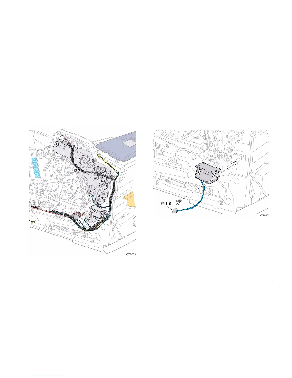
Figure 4 Wiring Harness Locations
REP 4.3 Tray 1 Pick Solenoid
Parts List on PL 4.1 Item 3
Removal
1. Remove the Control Panel Cover (REP 1.5).
2. Remove the Left Side Cover (REP 1.10).
3. Disconnect the Solenoid wiring harness connector P/J110 from the Left Side Harness.
4. Remove 1 screw (plastic, T-20) that secures the Solenoid to the Media Drive Assembly.
5. Remove the Tray 1 Pick Solenoid.
Figure 1 Removing the Tray 1 Pick Solenoid
Replacement
Align the hole in the Solenoid with the boss on the Media Drive Assembly before tightening the
screw.

 Loading...