October 2012
4-75
ColorQube 8570/8870 Service Manual
REP 4.7, REP 4.8
Repairs and Adjustments
Xerox Internal Use Only - Revised, 3rd Revision
REP 4.7 Electronics Module Fan
Parts List on PL 4.1 Item 7
Removal
1. Remove the Control Panel Cover (REP 1.5).
2. Remove the Left Side Cover (REP 1.10).
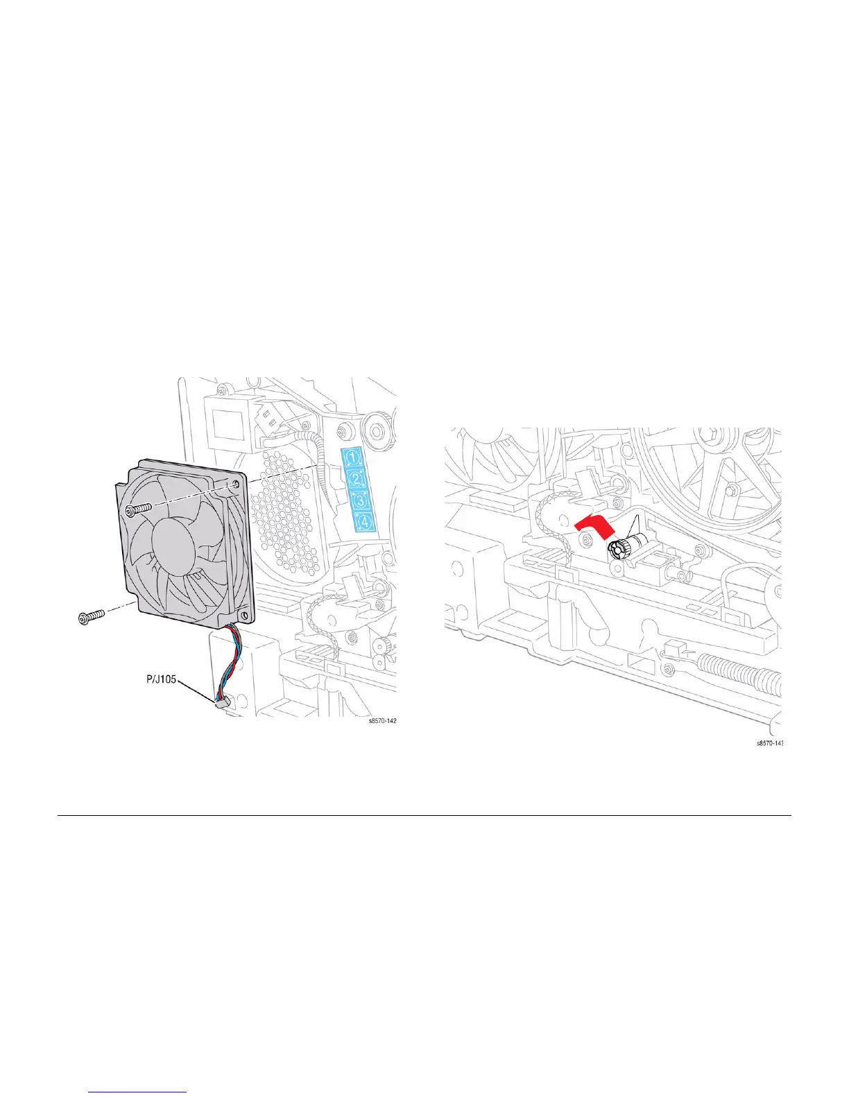
3. Disconnect the Fan wiring harness connector P/J105 from the Left Side Harness.
4. Remove 2 screws (plastic, T-20) that secure the Electronics Module Fan to the chassis.
5. Remove the Electronics Module Fan.
Figure 1 Removing the Electronics Module Fan
REP 4.8 Head Tilt Gear
Parts List on PL 4.1 Item 8
Removal
1. Remove the Control Panel Cover (REP 1.5).
2. Remove the Left Side Cover (REP 1.10).
3. Remove the Right Side Cover (REP 1.11).
4. Remove the Exit Cover (REP 1.7).
5. Remove the Ink Loader (REP 1.8).
6. Remove the Funnel Cap (REP 2.1).
7. Remove the Jetstack Cap (REP 2.2).
8. Remove the Printhead (REP 2.3).
9. Remove the KL-Clip from the left side.
Figure 1 Removing the KL-Clip
10. Remove the Waste Tray (REP 1.15).
11. Remove the X-Axis Bias Spring (REP 2.24).

 Loading...